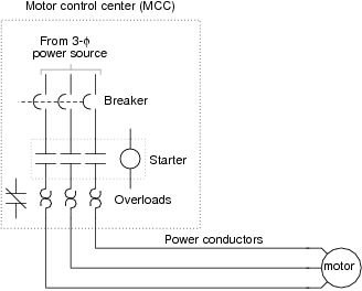
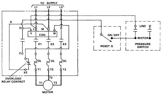
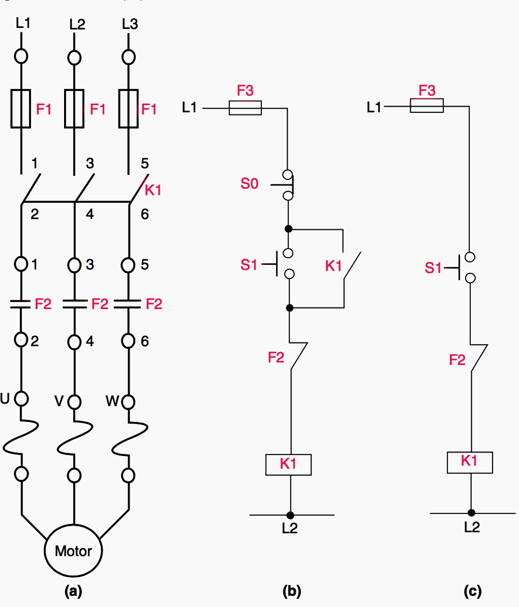
Working principle of dol starter. A single phase dol motor starter can be designed using the same components as shown in following diagram.
Push On Start Stop Wiring Diagram H1 Wiring Diagram
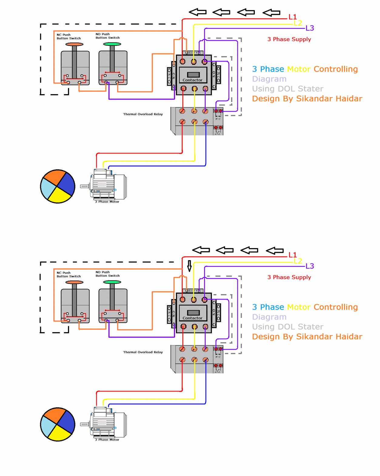
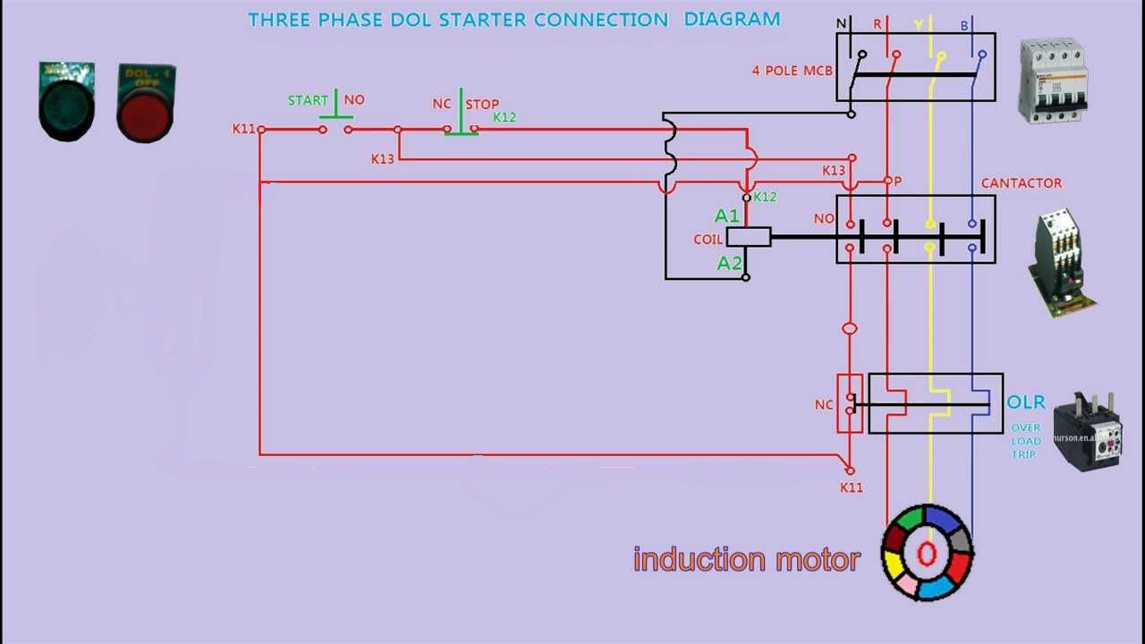
Dol starter panel wiring diagram. In the below dol starter wiring diagram i shown a molded case circuit breaker a magnetic contactor normally open push button normally close push button switch thermal overload relay motor trip indicator and 3 phase motor. Which is easy made my a 3 pole or 4 pole mcb miniature circuit breaker or mccb molded circuit breaker magnetic contactor motor overload protection. Wiring diagram of dol starter. Direct on line starter wiring diagram. The main heart of dol starter is relay coil. Dol starter wiring diagram yes this post is about to understand the 3 phase motor dol starter wiring connection.
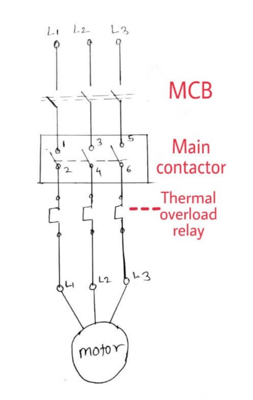
All connection i shown with complete guide. Single phase dol starter wiring diagram. Reverse forward motor starter control and power circuit with diagram motor windingstar delta starterdol starterstar delta connection3 phase dol starter connection diagram direct online starter. We have to use all 3 poles of the overload relay otherwise the imbalance due to the current flow in only 2 of them will cause unnecessary tripping. A wiring diagram of a dol starter is shown below. Sometimes known as an across the line starter this type of motor controller is used as a simple starter for larger electric motors providing.
In the above three phase dol starter wiring diagram. A dol starter is a direct on line motor starter. For small load three phase motor the common controlling device is dol starter. Normally it gets one phase constant from incoming supply voltage a1when coil gets second phase relay coil energizes and magnet of contactor produce electromagnetic field and due to this. Since the dol starter connects the motor directly to the main supply line the motor draws a very high inrush current compared to the full load current of the motor up to 5 8 times higher.

