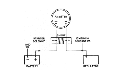
In this video i show how to properly wire an ammeter amp gauge with a shunt to measure amps. It is connected in series because the flow of current within the series circuit is the same.

Ammeter Shunt 1964 Nova Ss 1964 Chevelle Ss
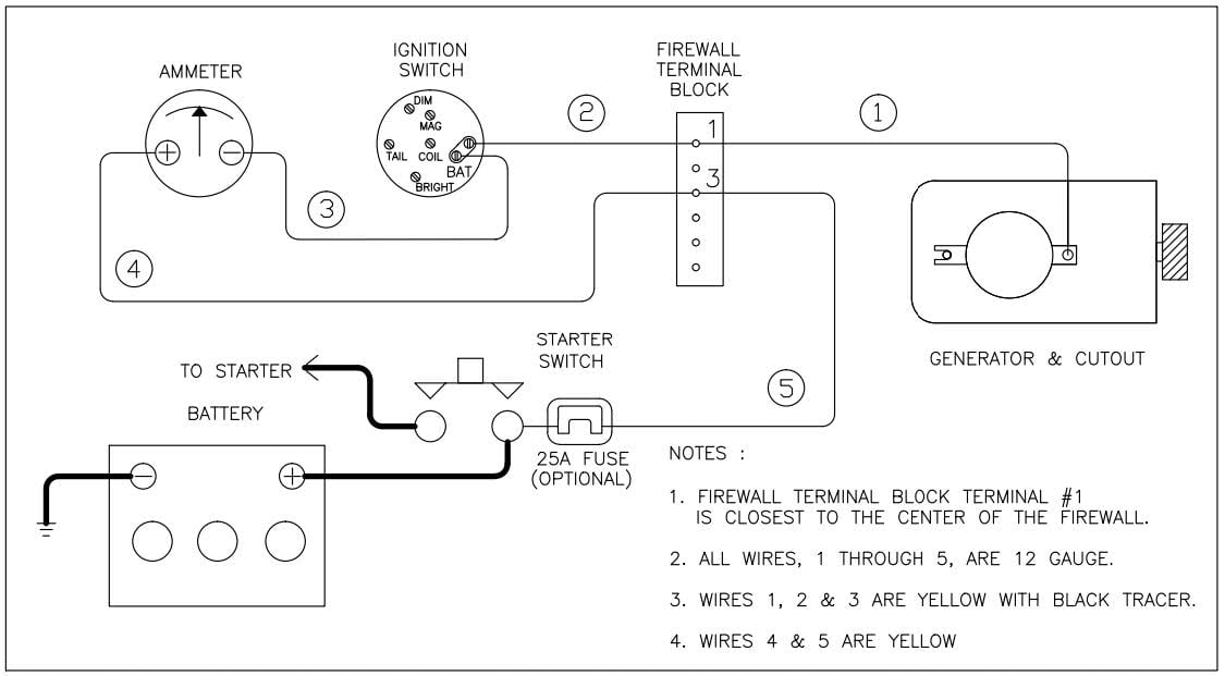
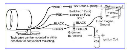
Wiring diagram for ammeter. 2 wire minimum with an insulation temperature rating of 220 f 105 c minimum from the battery. Use the flashlight or drop light to see the wiring under the dash. Ill show you how. Take your other piece of red 14 gauge wire and connect it to the other terminal of the ammeter. An ammeter from ampere meter is a measuring instrument used to measure the current in a circuitelectric currents are measured in amperes a hence the name. Then locate any wire that has power with the ignition off.
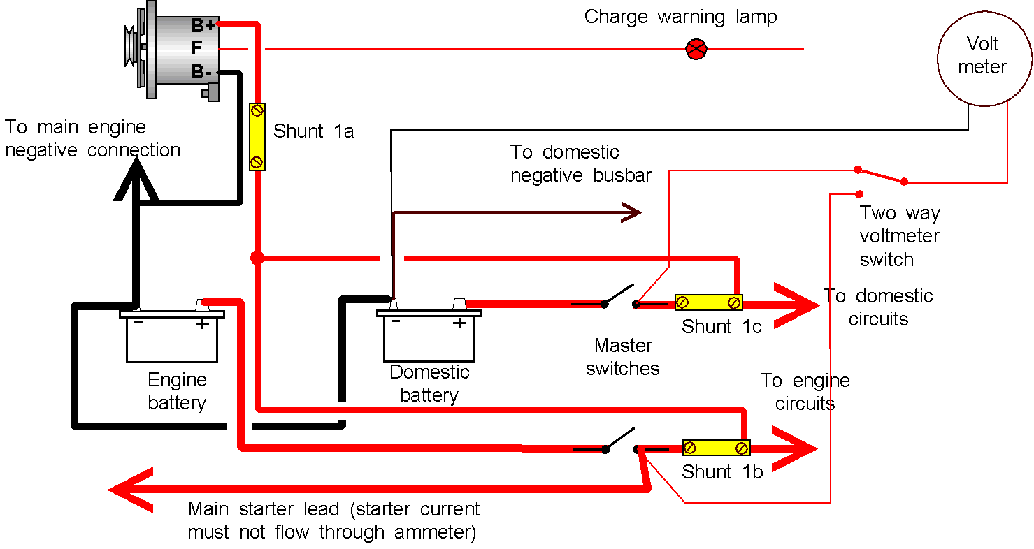
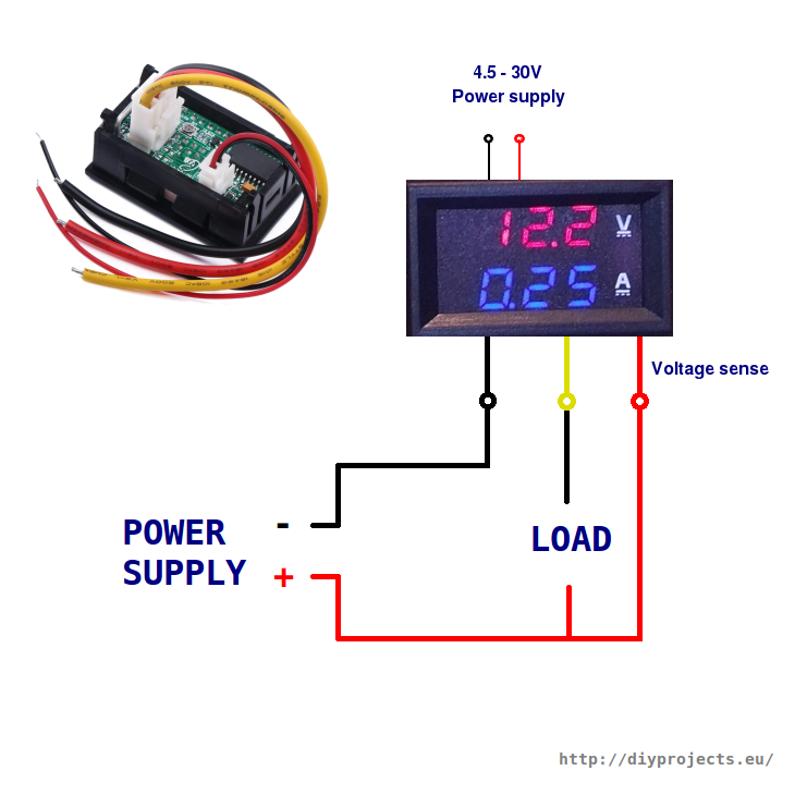
Wiring for ammeter or voltmeter. Of the alternator to the left terminal on the ammeter see wiring diagram. Ammeter shunt wiring diagram new digital volt amp meter wiring whats wiring diagram. Connect an 8 awg 100 mm. Wiring representations are made up of 2 points. A wiring diagram is a type of schematic which utilizes abstract pictorial signs to show all the affiliations of elements in a system.
With your positive battery terminal now connected to the ammeter you are ready to connect the next wire. Once you have connected it to the ammeter you will then connect it to the alternator terminal. Step 4 connect the ammeter to the alternator. The working principle of an ammeter mainly depends on resistance as well as inductive reactance. Instruments used to measure smaller currents in the milliampere or microampere range are designated as milliammeters or microammetersearly ammeters were laboratory instruments which relied on the earths magnetic field for operation. The ammeter shows direction and rate of current to and from the battery.
How to wire ammeter and volt meter amp meter diy duration. Bought an ammeter and shunt from china with no instructions how to wire it. This will be higher after starting but probably never. A short description of how to wire in an ammeter or voltmeter for your car from someone who understands the principles. Under normal conditions the meter should show a small charge. The main function of this device is to measure the flow of current with the help of a.
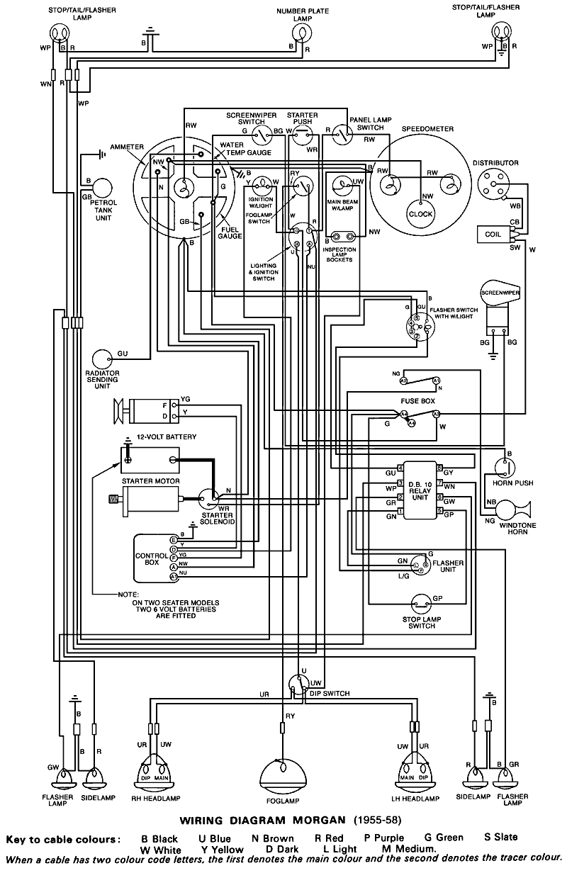
Wiring diagram for volt tef 20 key a starter motor 1 yellow b dynamo 2 green black c control box 3 yellow black d ammeter 4 white e starter switch 5 battery cable f heater switch g heater coil h connection to light switch i 2 x 6 volt batteries jja 25th june. Icons that stand for the parts in the circuit as well as lines that stand. Use the wiring diagram and test light or multi meter to locate the positive wire from the alternator to the fuse block. This device includes extremely less impedance because it must include less amount of voltage drop across it. Alternator demo wiring connection to battery capacitors inverter modification duration.
