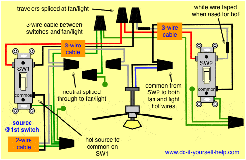
The following image shows a typical spdt toggle switch with its terminals. The principle is that the switch will have one main input terminal and two output terminals.

Z Wave 4 Way Switch Wiring Diagram H1 Wiring Diagram
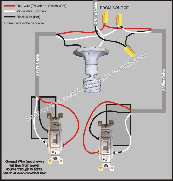
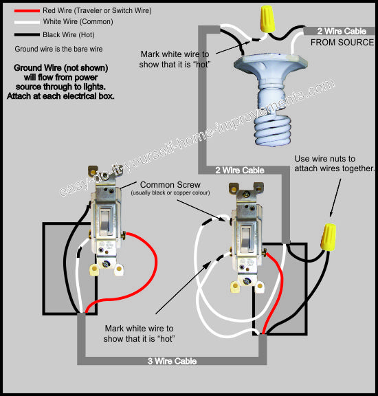
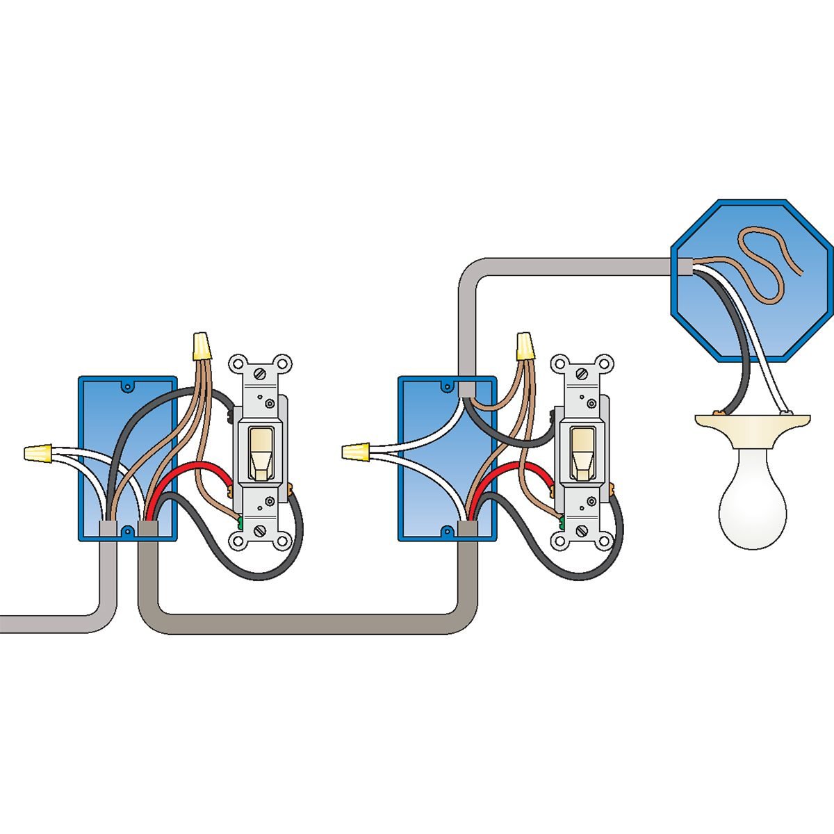
Typical 3 way switch wiring. The typical 3 way switch wiring has two screw terminals at one end of the switch. In the 1st diagram below a 2 wire nm cable supplies power from the panel to the first switch box. Typical 3 way switch wiring nm cable. A dimmer switch is wired the same way as a single pole switch. Wiring a 3 way light switch. With a pair of 3 way switches either can make or break the connection that completes the circuit to the light.
Wiring a 3 way light switch is certainly more complicated than that of the more common single pole switch but you can figure it out if you follow our 3 way switch wiring diagram. This is where the travelers are connected. See the description of each one of them below. Pick the diagram that is most like the scenario you are in and see if you can wire your switch. This feature is not available right now. A 3 way switch circuit is explained and described in detail including visual animation and practical application.
In each position onoff the switch will connect the input to only one of the outputs. A typical three way switch will have you guessed it three terminals. 3 way switch wiring diagram. The opposite end of the switch has one screw terminal which may be a different color as seen here in this photo. This might seem intimidating but it does not have to be. Three wire cable runs between the switches and the outlet.
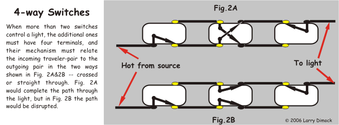
The spdt toggle switch can be considered as a two way light switch as it has three terminals and works very similar to the two way light switch. Take a closer look at a 3 way switch wiring diagram. Please try again later. A 3 wire nm connects the traveler terminals of the first and second 3 way switch together. This circuit is wired the same way as the 3 way lights at this link. Video includes the bonus addition of adding a 4 way switch.
For wiring i have selected the standard way with a 37v lithium ion battery as the power supply. A visual tour of wiring 3 way switches. Traveler wires are interchangeable. In this illustration you can see the red hot lead wires of the dimmer are connected to the inbound black wire from the electrical source the electrical panel and the black wire that goes to the light fixtures black wire which in this case is a white wire that has been taped with black electrical tape. Depending on your wiring configuration this single terminal will have attached either the power line or. 3 way switched outlet wiring.
With these diagrams below it will take the guess work out of wiring. In other words the current will always flow. The black line wire connects to the common terminal of the first 3 way switch. In this diagram two 3 way switches control a wall receptacle outlet that may be used to control a lamp from two entrances to a room.
