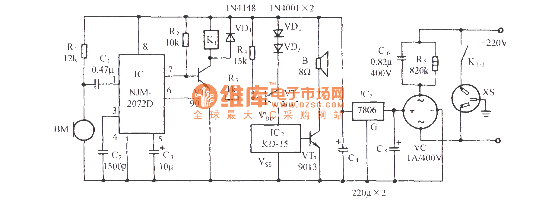
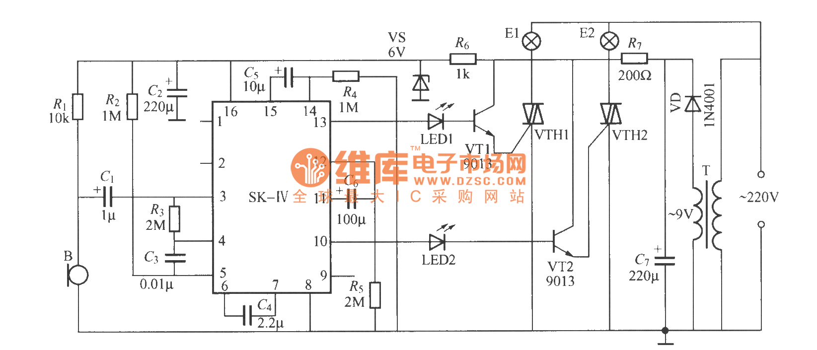
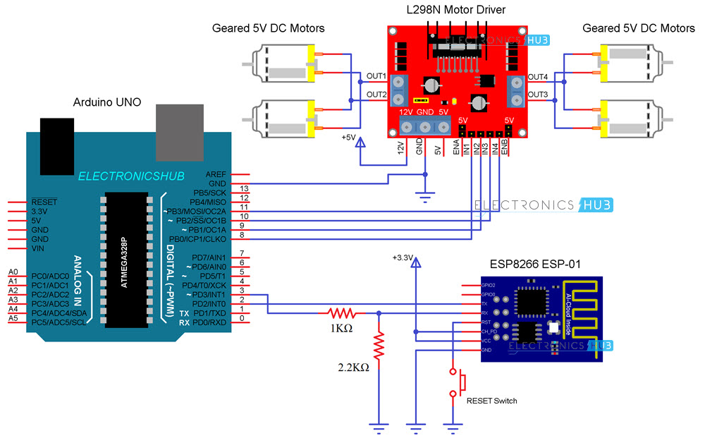
Circuit diagram and explanation. 6 and its components layout in fig.
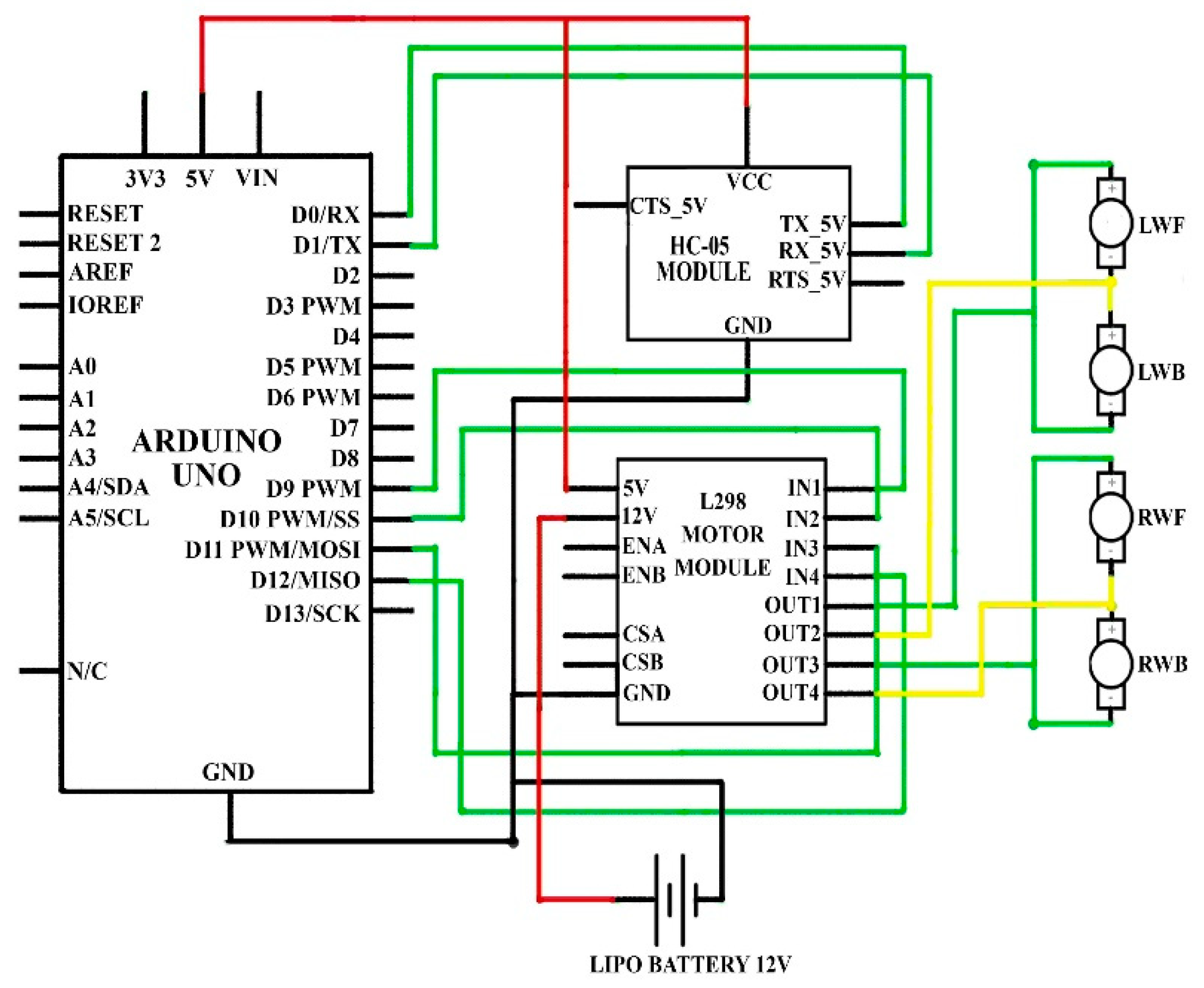
Sensors Free Full Text Single Equipment With Multiple
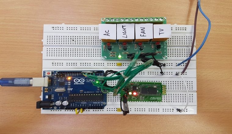
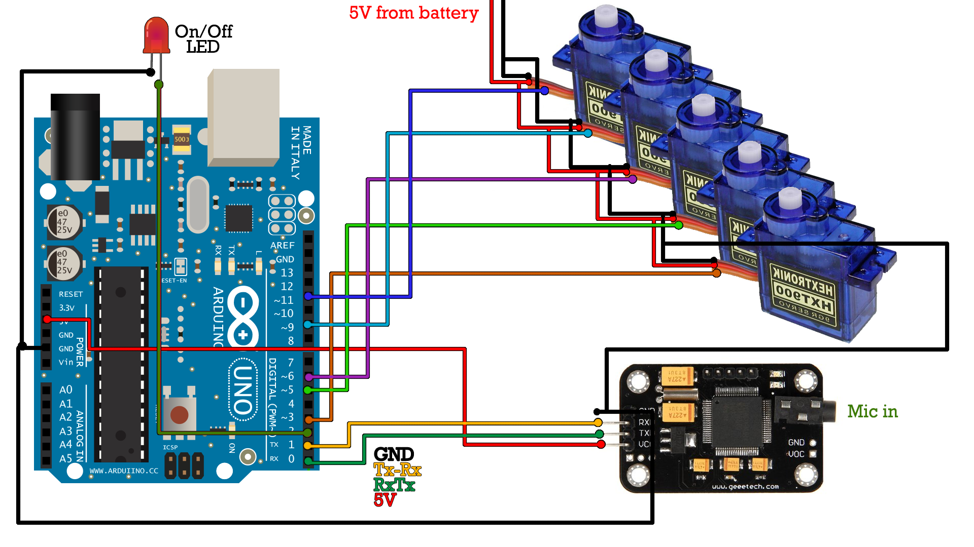
Voice control circuit diagram. Voice commands are used to control different appliances. Working of the project. This project is similar to home automation using bluetooth. The tx rx pins of arduino is connected to rx tx pins of bluetooth module. Upload source code voicectrlino to the board. In that project we use the s2 terminal application in this we use amrvoice application.
The app is developed in such a way that it convert the voice command to text and transfer the text to the connected bluetooth device. This project is the part of my home automation series. In this project we are using a voice function to control home devices. The bluetooth connected on the arduino board receives text from the android app as characters and stored them as string to the assigned. Circuit diagram for this voice controlled lights is given below while uploading the code in the arduino uno disconnect the rx and tx pins and connect again after the code is uploaded. It is good projecti was start to do it but it cant be work for me.
Here we are explaining few parts of code. A motor driver is connected to arduino to run the car. All the necessary connections are explained in the circuit diagram. Hello guysthis is our project. May 8 2019 at 1249 pm. In this project a simple voice activated home automation system is designed.
Code and explanation. This application is. Thats called voice control robot thats controlled bluetooth hc 05 via a smartphone app. This is a simplified version of any other voice control robot no complex coding easy to understand coding with easy algorithmthe app is developed in such a way that it convert the voice command to text and transfer the text to the connected blue. All the connections are made as per the circuit diagram above. Please help me send code for me.
November 17 2018 at 1038 pm. Circuit diagram connections the circuit consists of arduino uno board hc 05hc 06 bluetooth module l293d motor driver ic a pair of dc geared motors of 200 rpm and a 9v battery. Voice controlled home automation using arduino. A pcb layout of the receiver circuit for voice controlled robotic car is shown in fig. A micromax q372 android smartphone with android lollipop 50 was used to run voicecontrol app. May 28 2018 voice controlled leds circuit diagram using arduino and bluetooth.
How to make a voice control direction control remote control android and arduino robot 3 in one. Circuit diagram for bluetooth controlled car is shown in above figure. The complete arduino code for voice controlled leds is given at the end. We will now see the working of the project. Motor drivers input pins 2 7 10 and 15 are connected to arduinos digital pin number 12 11 10 and 9 respectively. Sir using two motor voice control robot ka circuit diagram and working send or upload plz.

