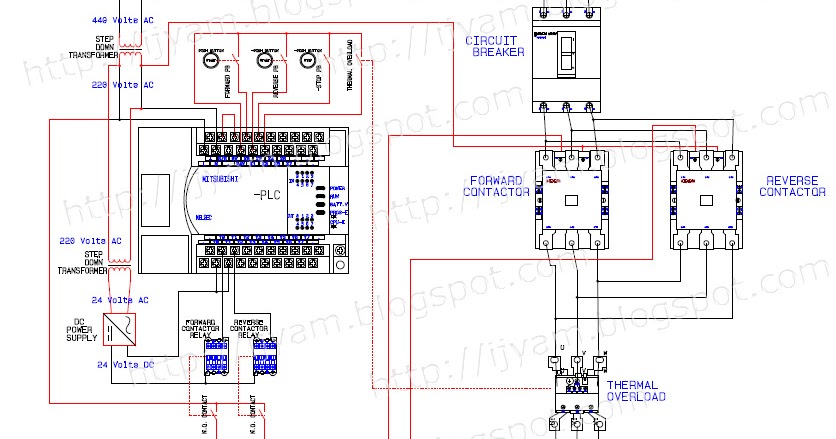
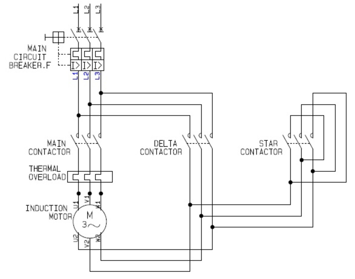
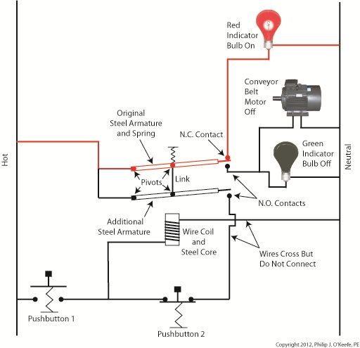
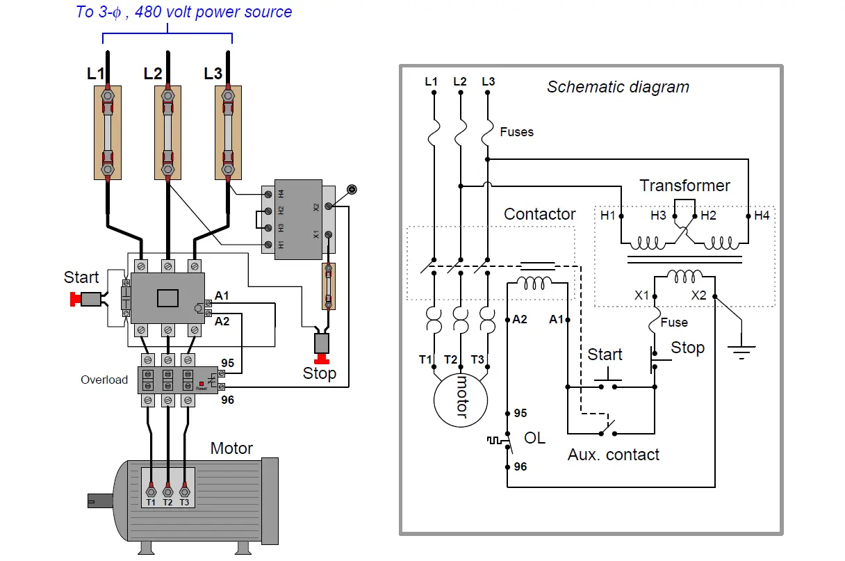
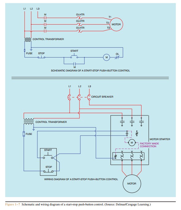
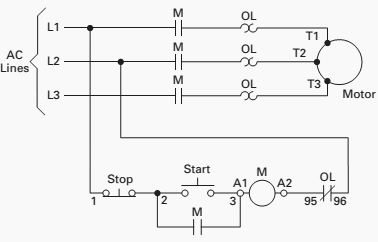
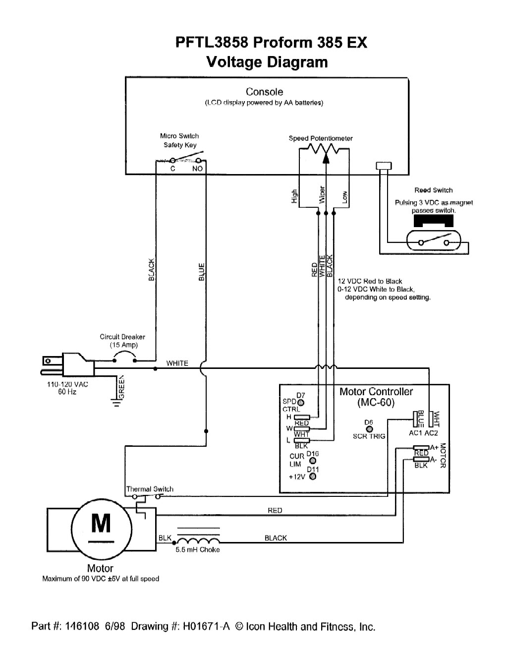
They can be used as a guide when wiring the controller. Once again this system could be automated by replacing the start and stop pushbutton switches with process switches eg.
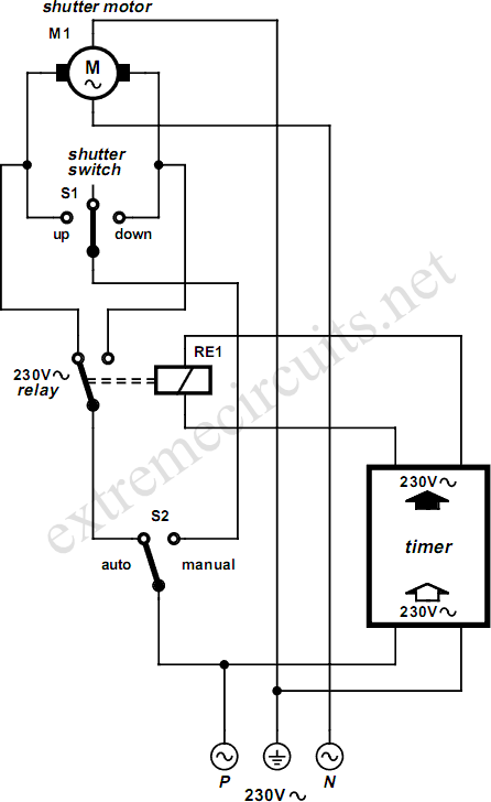
Rolling Shutter Motor Control Circuit Diagram
Wiring diagram of motor control. In the next episode in this series of videos we will add multiple start stop stations and demonstrate via the onscreen live simulated schematic how they work in the motor control circuit wiring. The control circuit is separate from the motor circuit. We use 2 magnetic contactors as forward reverse switch. If the volt ages are different it is called separate control. Figure 1 typical wiring diagram. Typical starter wiring diagram three phase.
Variety of motor control panel wiring diagram. Figure 1 is a typical wiring diagram for a three phase magnetic motor starter. They show the relative location of the components. The control circuit may not be at the same voltage as the power circuit. In the above one phase motor wiring i first connect a 2 pole circuit breaker and after that i connect the supply to motor starter and then i do cont actor coil wiring with normally close push button switch and normally open push button switch and in last i do connection between capacitor. A wiring diagram is a simplified traditional photographic representation of an electrical circuit.
Forward reverse motor control diagram for three phase motor for three phase motor forward reverse control circuit. Square d motor starters wiring diagram sq d motor starter wiring diagram square d 3 phase motor starter wiring diagram square d 8536 motor starter wiring diagram every electric structure is composed of various distinct pieces. Basic wiring for motor control technical data. When the voltage of the control and power circuits is the same it is referred to as common control. It reveals the parts of the circuit as streamlined shapes and the power and also signal links in between the gadgets. Pressure switches for an air compressor control system to make a system that starts and stops automatically.
Three phase motor connection stardelta y δ reverse forward with timer power control diagram starting stopping of 3 phase motor from more than one place power control diagrams control 3 phase motor from more than two buttons power control diagrams. If not the structure wont work as it ought to be. The above diagram is a complete method of single phase motor wiring with circuit breaker and contactor. In the diagram i connect the incoming three phase supply l1 l2 l3 to the mccb circuit breaker molded case circuit breaker. Most onoff motor control circuits in the united states are some variation on this wiring theme if not identical to it. Each part should be placed and linked to different parts in specific way.
Here i showed the forward reverse wiring diagram. Motor control wiring diagram pdf wiring diagram is a simplified usual pictorial representation of an electrical circuitit shows the components of the circuit as simplified shapes and the facility and signal associates with the devices.
