When looking at a vfd wiring system there are several aspects that need to be consider due to interaction between various wiring in the system itself. It reveals the components of the circuit as simplified forms and also the power as well as signal connections in between the gadgets.
Vfd Wiring Diagram Pqrstu Giant Slotenmaker Janwillem Nl
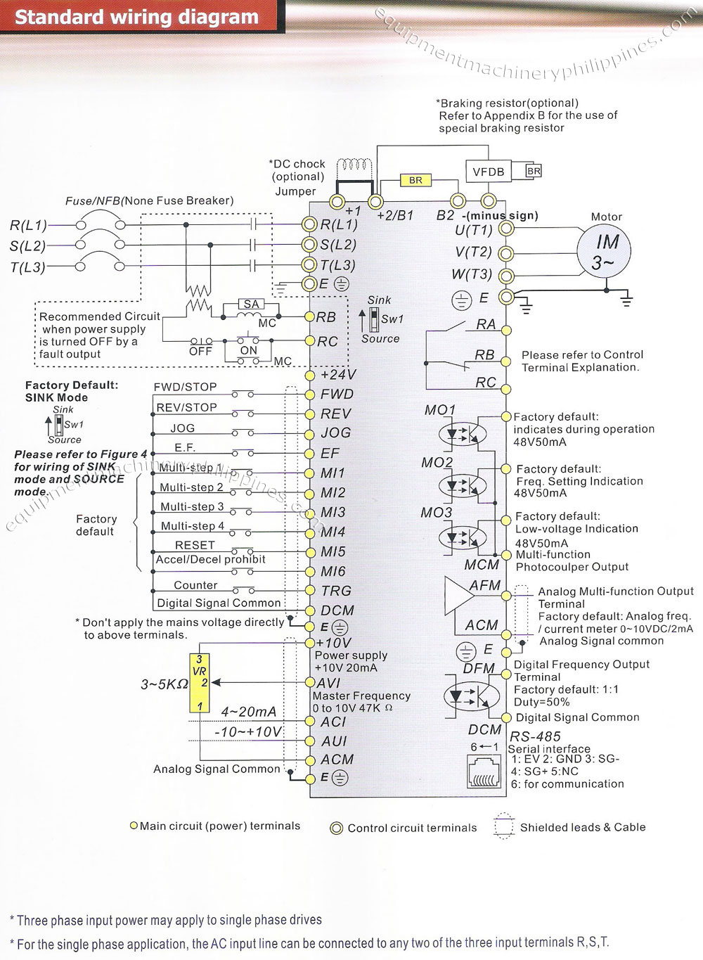
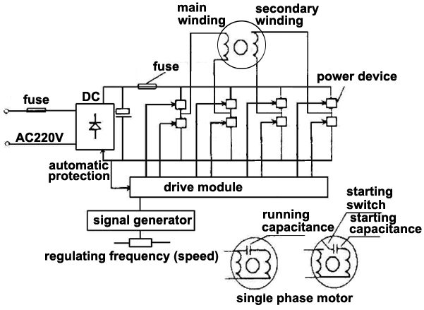
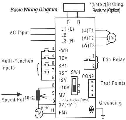
Vfd connection diagram with motor pdf. A basic vfd system generally consists of an ac motor a controller and an operator interface. Main circuit wiring the vfd main circuit terminals shown as below figure. Change speed of motor 3 phase 2. Check connections of l1 l2 l3. Do different function on motor operation like jog accedeacc time taking feed back up. Diagram dd6 diagram dd7 m 1 ln e diagram dd8 ln e l1 l2 l3 sc z1 u2 z2 u1 cap.
Motor develop constant rated torque from low. If the vfd system has bypass there will be an overload device for the bypass circuit but if tripped will also prevent the vfd connect to the motor. With motor cables and control cables. Vfd start stop wiring diagram. Make sure if you have a bypass function that both the vfd and bypass mode operate the motor in the same direction. These are outlined below.
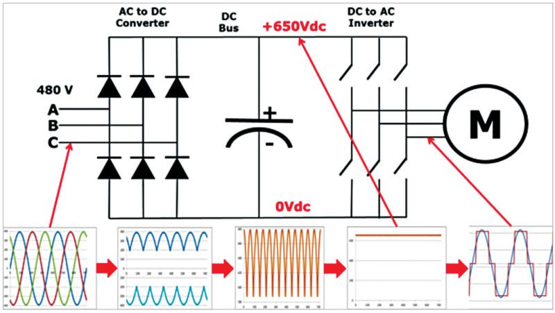
Thermal contacts tb white m 1 z2 yellow z1 blue u2 black u1 red bridge l1 and l2 if speed controller sc is not required m 1 ln e. Pin out connection diagram for vfd m fig. 1 the vfds three phase ac input terminals rl1 sl2 tl3 the power lines input terminals connect to 3 phase ac power through line protection or leakage protection breaker it does not need to consider the connection of phase sequence. Diagram dd5 two speed motors for all other single phase wiring diagrams refer to the manufacturers data on the motor. I am here with giving you a vfd start stop wiring diagram for running a vfd through panel board push button and keypad of the vfd it is called hmi. Motor rated voltage 400 v motor rated frequency 87 hz.
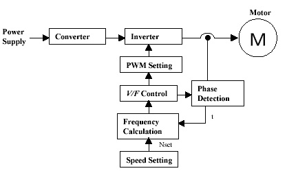
Switch on the 3 phase power supply. Test the vfd without a motor to possibly isolate a problem vhz. Vfd for ac motors have been the innovation that has brought the. Electromagnetic interference emi can be carried on the ground back to the drive via the ground connection shown above. Change direction of motor 3. Vfd is shorted for variable frequency drive also known as ac drives and inverters thats used to make an ac motor working in variable speed among other parametersthis is definition used in all topical discussion on this paper.
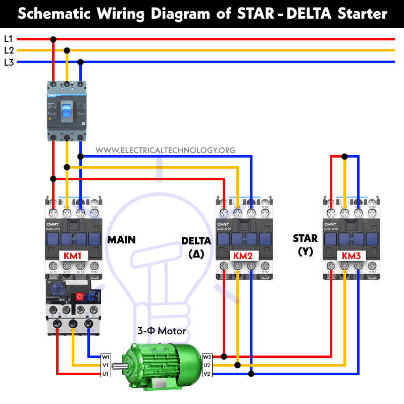
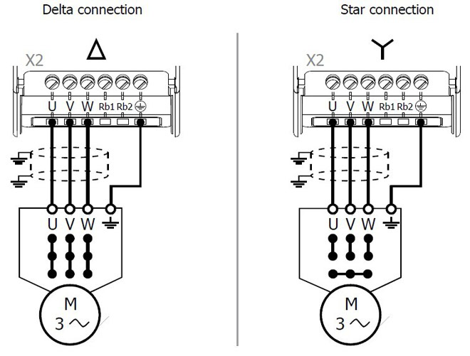
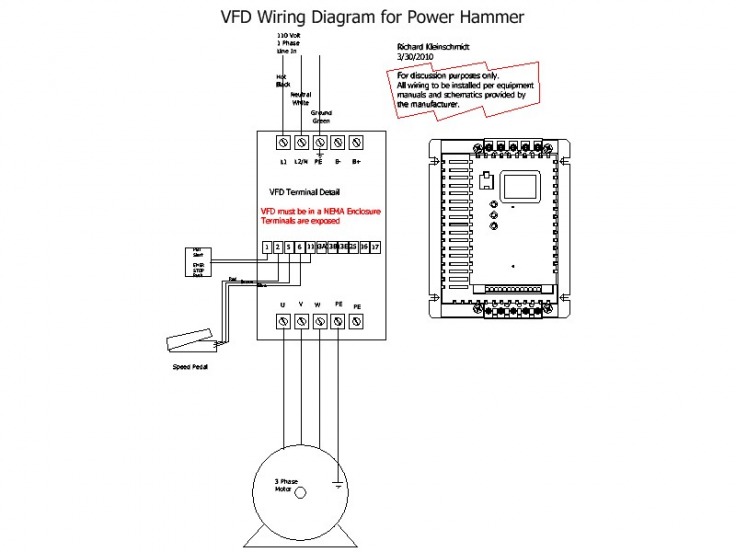
Vf line comes through rated motor point 230 v 50 hz to maximum point 400 v 87 hz with correct ratio. T1 t2 t3 used for giving 3 phase input to vfd and connecting motor to it and wires coming out of m0 m1 and gnd. For programming the vfd m. Rated vfd output current not less than motor current in delta connection. A wiring diagram is a streamlined traditional pictorial representation of an electrical circuit. Vfd is a short form of variable frequency drive or variable voltage variable frequency drivethe vfds are working based on changing the input frequency and input voltage of the motor we can change the speed of the.
Collection of abb vfd wiring diagram. Vfd variable frequency drive used for 1. Set in vfd parameters motor data as follows. Controlling a digital keypad on delta vfd m steps for complete motor control.
Gallery of Vfd Connection Diagram With Motor Pdf