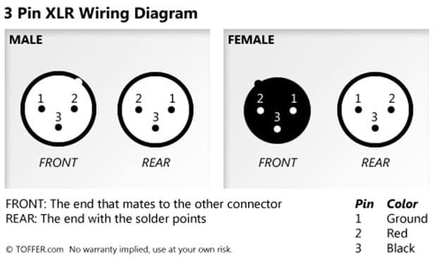
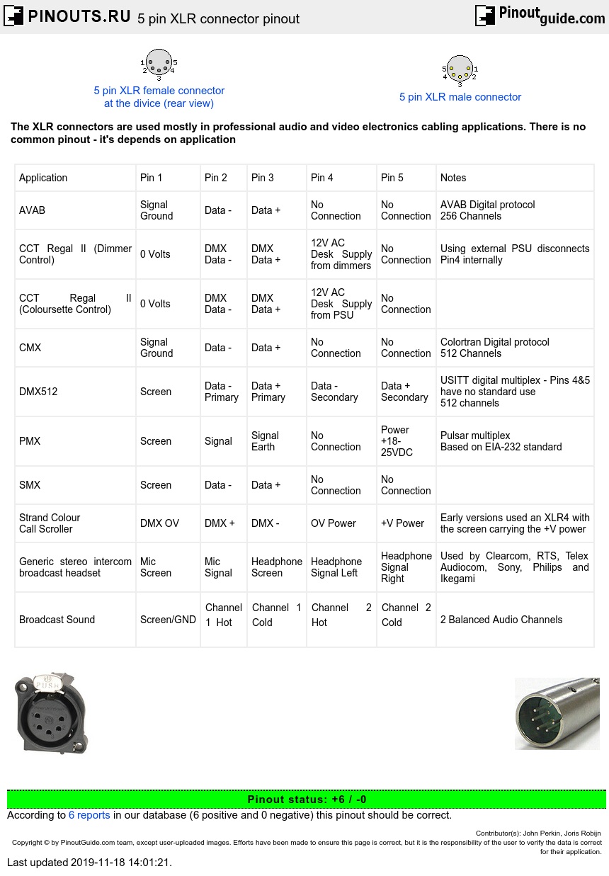
The above diagram shows you the pin numbering for both male and female xlr connectors from the front and the rear view. A wiring diagram is a streamlined conventional photographic depiction of an electric circuit.

Xlr Male Wiring Diagram H1 Wiring Diagram
Xlr male to female wiring diagram. On two male 3 pin xlr connectors with the. Visit the post for more. Xlr pinout balanced a balanced system is used in pro audio systems xlr wiring diagram shown below with an overall screen covering a twisted pair. Adsinfeedtxt balanced xlr rca wiring diagram wiring diagram. It reveals the components of the circuit as streamlined shapes and the power as well as signal links between the devices. The speaker cable contains 2 conductors with a section of 1mm².
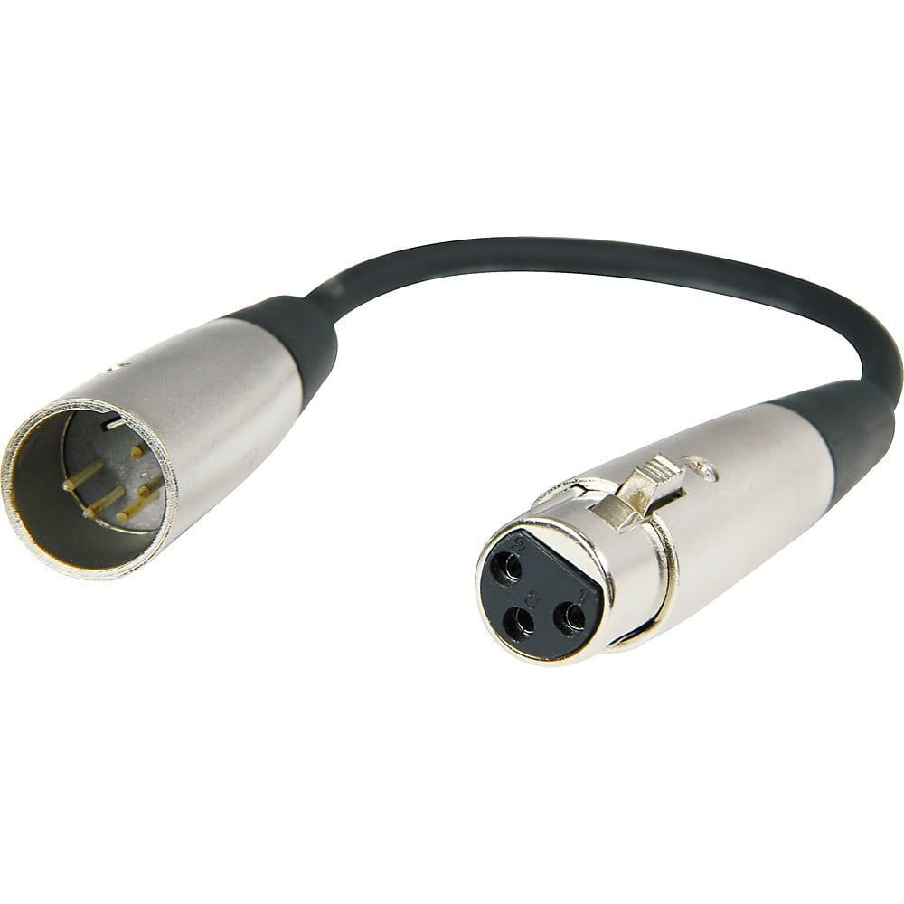
Gereton 6 packs cable for all xlr accessories 3ft wiring cable xlr male to xlr female color cable 3 balanced snake line 3ft patch cable cords 1999 19. 3 pin xlr wiring diagram cable wiring etc cable designed for being cut into standard mic cables may have 2 pairs of wire and a shield around the outside in that case pair the colors together and make sure they go to the same pin number on each end. Xlr to 1 4 wiring diagram this is images about xlr to 1 4 wiring diagram posted by janell a. The cla595 is a xlr male to xlr female connector cable that are ideal for solving connections with old speaker and amplifier systems. Here are the dmx 512 pinouts for each. The above diagram shows you the pin numbering for both male and female xlr connectors from the front and the rear view.
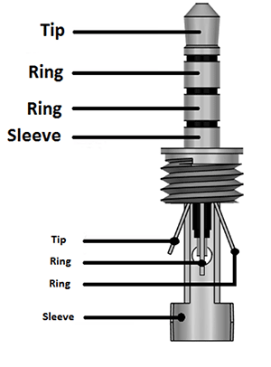
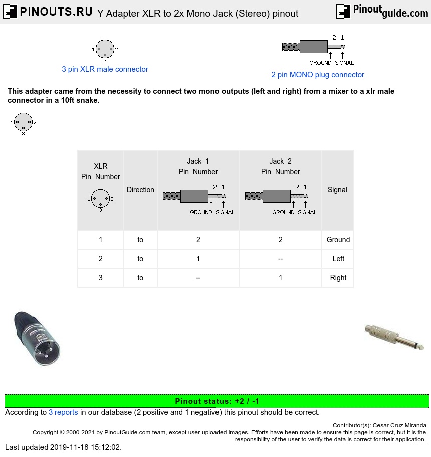
Per the standard dmx uses 5 pin xlr with male being input and female being output. 3 pin xlr connectors are standard amongst line level and mic level audio applications. Xlr connector wiring diagram together with 3 pin mini 5 pin xlr wiring diagram for center u2022 4 dmx diagrams rh gregorywein co 3 female end cable wiring xlr cable wiring diagram. Collection of xlr to mono jack wiring diagram. 3 pin xlr wiring standard. Xlr plug wiring diagram how to wire a mono audio signal to a 3 5 trs stereo jack also headphone wiring diagram.
The surrounding shield should be soldered to pin 1. There are also numerous other connection types such as 3 pin rj45 etc. The stereo analogue input is on two female 3 pin. Pin 2 on the xlr is hot and carries the positive going signal whilst pin 3 is cold and provides the return. Bueno in xlr category on nov 20 you can also find other images like wiring diagram parts diagram replacement parts electrical diagram repair manuals engine diagram engine scheme wiring harness fuse box vacuum diagram timing belt. The xlr connector is a style of electrical connector primarily found on professional audio video and stage lighting equipment.
The rear view is the end you solder from here are the connections on each pin.
