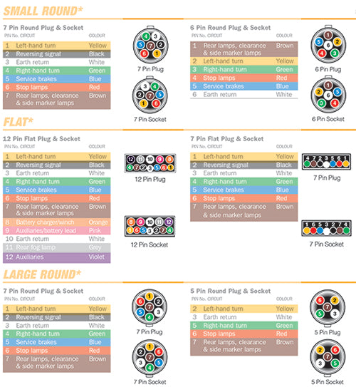
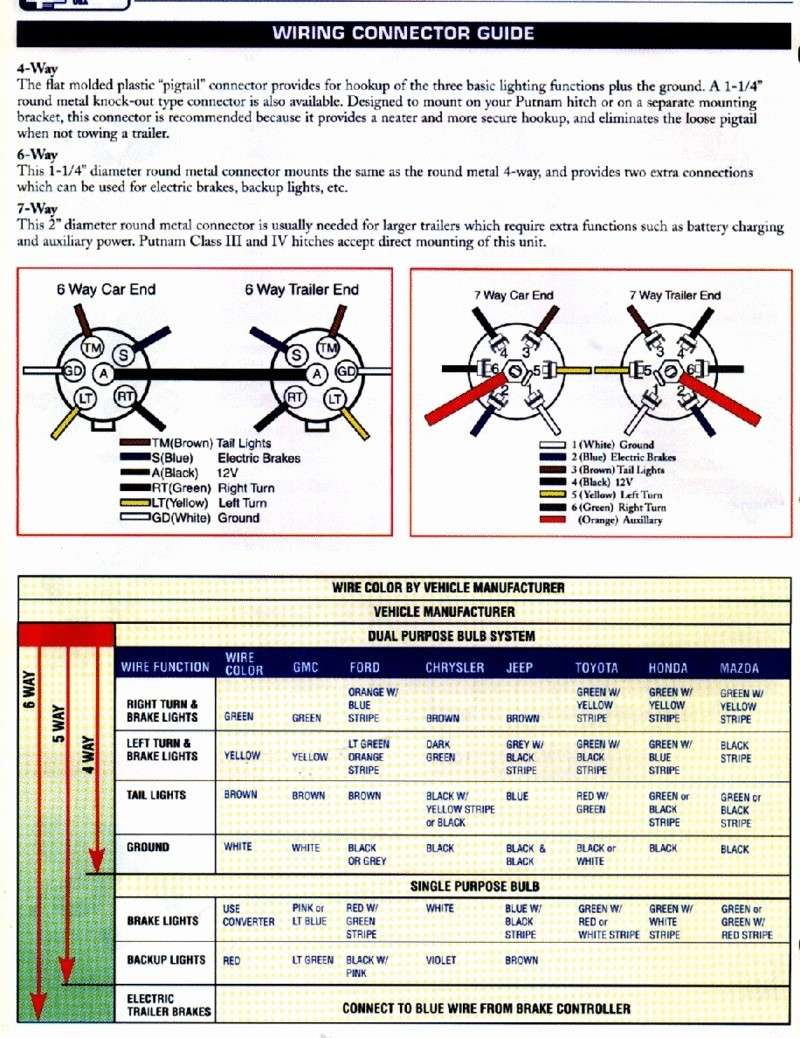
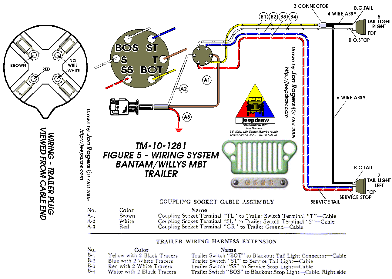
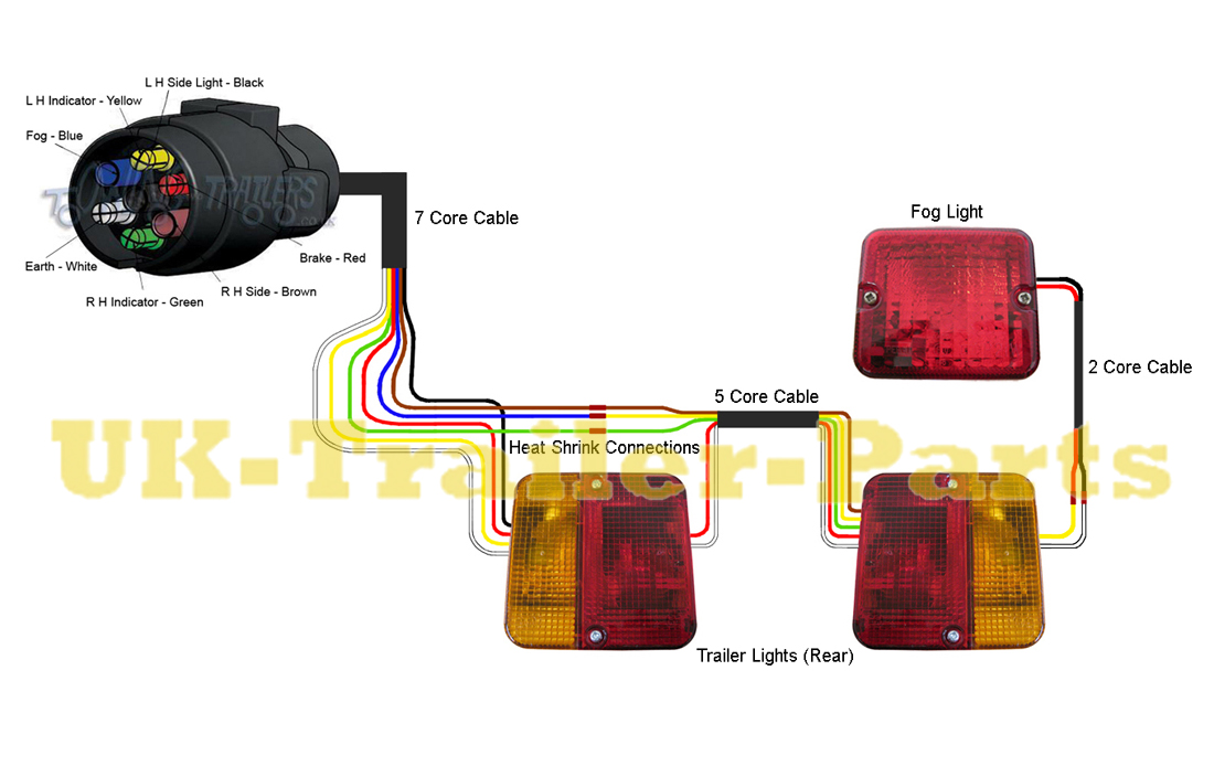
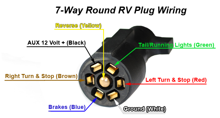
Before beginning this installation check your vehicles owners manual andor the service manual to familiarize yourself with the wiring of the rear lights on your vehicle. 4 way trailer connectors are.
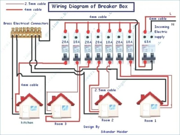
Rm4 Wiring Diagram Wiring Diagram Images
Wiring diagram for trailer lights south africa. 5 way trailer wiring diagram allows basic hookup of the trailer and allows using 3 main lighting functions and 1 extra function that depends on the vehicle. They also provide a wire for a ground connection. An extra pin allows using another extra function. Some trailer builders just connect this wire to the frame then connect the ground from all the other lights and accessories to the frame as well. The source is at sw1 and 2 wire cable runs from there to the fixtures. 1 2 3 4 5 6 7 wiring diagram tailgate trailer sabs 1327 1981 1 left indicator yellow 1 2 auxiliary blue 3 earth white.
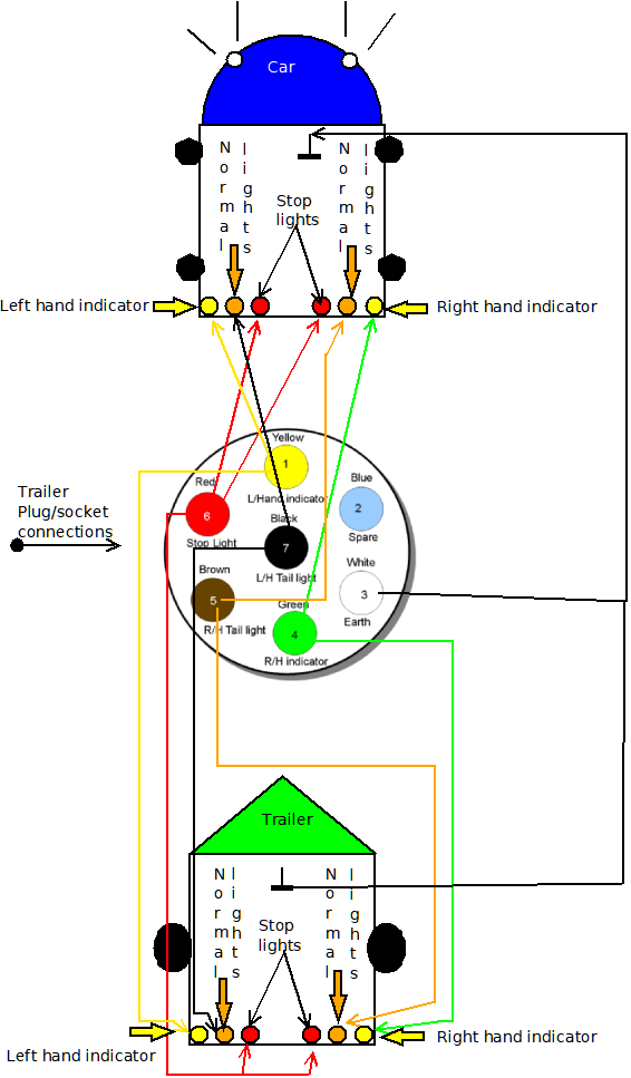
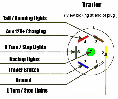
Also it must connect with things if included that use the aux power and back up lights too. Venter nosecone and fridges. The hot and neutral terminals on each fixture are spliced with a pigtail to the circuit wires which then continue on to the next light. With any 12v tester see photo at the bottom you can determine which wire from the trailer must be connected to the stop light wire. This is the view from the rear as you look at the terminals to wire the plug or socket. If you have a modern caravan refer to the dealer as they may have an additional socket wired up to allow fridges etc to be run.
Since the caravan is likely to block your vehicles brake lights and turn signals trailer lights help ensure that safety isnt compromised when you tow. This allows you to connect up the wiring to tow a caravan or trailer. In all cases the terminals will be numbered. 4 way trailer connectors are typically used on small trailers such as boat snowmobile utility and other trailers that that do not use brakes. Multiple light wiring diagram. Caravan trailer wiring.
As the name implies they use four wires to carry out the vital lighting functions. The four wires control the turn signals brake lights and taillights or running lights. I can never find this diagram when i need it so here it is. This is a wiring diagram for a 12n 7 pin standard trailer socket. 5 wire trailer wiring diagram. This wire must then be connected to the trailers stop lightstrailer tester wire diagram to see a 7 pin trailer plugsocket wiring details this operation must be done to each wire you need for your trailer.
The trailer wiring diagram shows this wire going to all the lights and brakes. This diagram illustrates wiring for one switch to control 2 or more lights.


