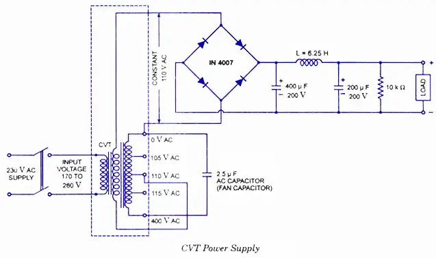
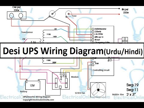
430 1212 chuan shun electric industrial company inc. The ac power 220v is entered to through input of transformer t1 to reduce voltage as 9vac then wire connected to four diode d1 d4 as bridge rectifier became to 11vdc.

Transformer Newbie Can I Use This Thing
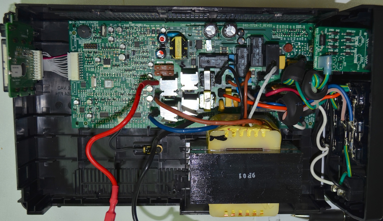
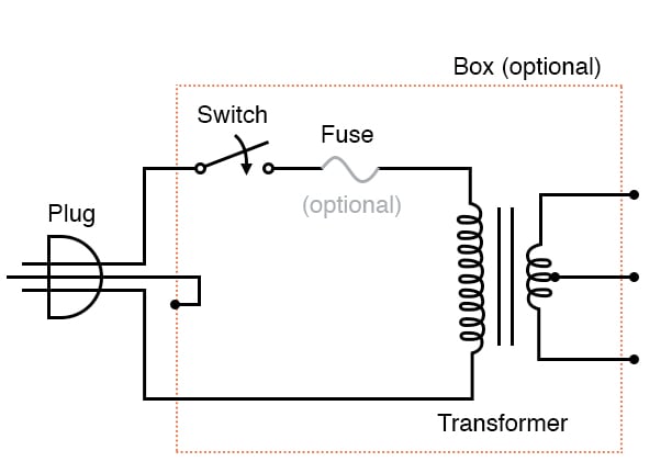
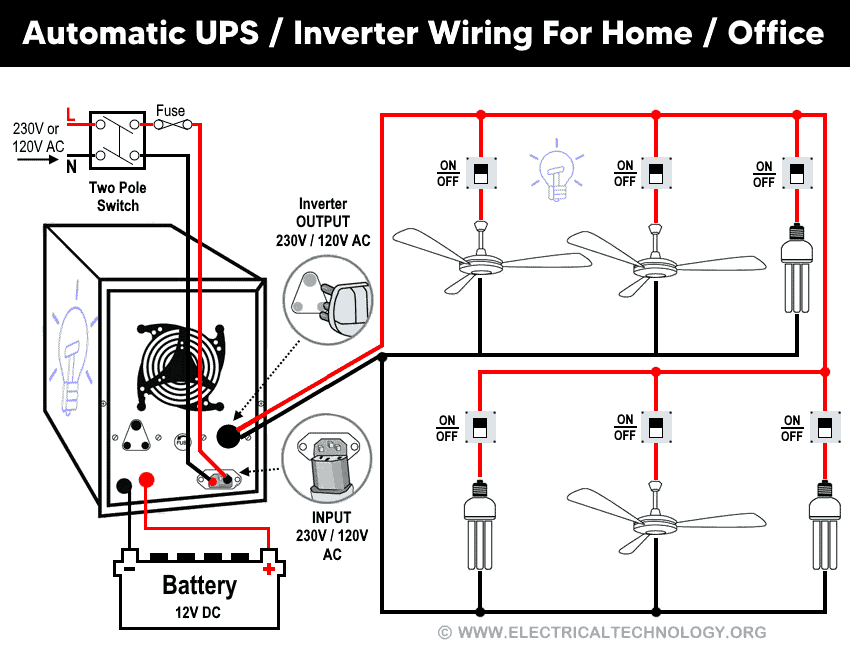
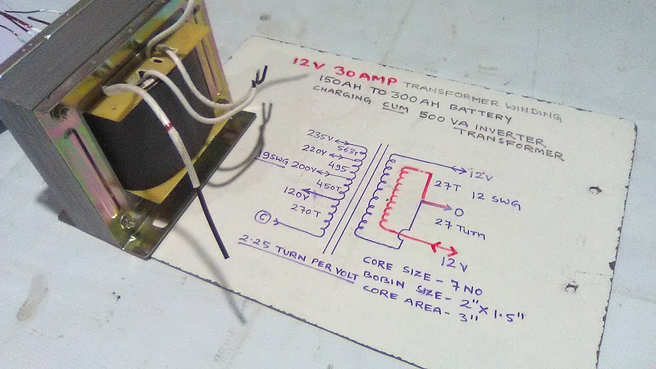
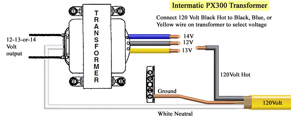
Ups transformer wiring diagram. The numbers printed on the side are as follows. Automatic ups system wiring diagram in case of some items depends on ups and rest depends on main power at office or home. Csc h1 e184733s class h 160º c can anyone tell me anything about a ups transformer or better yet about this ups transformer. Within the ups is a transformer very similar to the one in the attached picture. This simple and cheap 6 volt power supply circuits with a 6v backup battery system or 6v ups circuit diagram. If a voltage transformation is required having the transformer external to the ups system makes isolating the ups for maintenance easier.
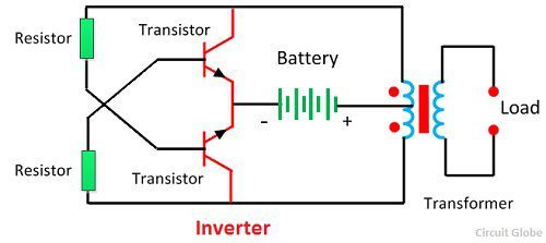
Related electrical wiring tutorial. The output of the ups may be at a different voltage than the loads. The circuit drawn pertains to a regular industrial ups uninterruptible power supply which shows how the batteries take control during an outage in electrical supply or variation beyond the normal limits of the voltage line without disruption on the operation providing a steady regulated output 5 volts by lm7805 and an unregulated supply 12 volts. Ups inverter wiring diagram with auto manual changeover switch system. Manual ups wiring diagram with change over switch system. Used to limit the fault current for downstream equipment.
Automatic ups system wiring circuit diagram for home or office new design with one live wire also read. Now according to the below ups connection diagram connect an extra wire phase to those appliances where we have already connected phase and neutral wires from power house db ie two wire as phase live as shown in the below fig.
Gallery of Ups Transformer Wiring Diagram