The transformer is very simple in construction and consists of magnetic circuit linking with two windings known as primary and secondary windings. It reveals the elements of the circuit as streamlined shapes as well.

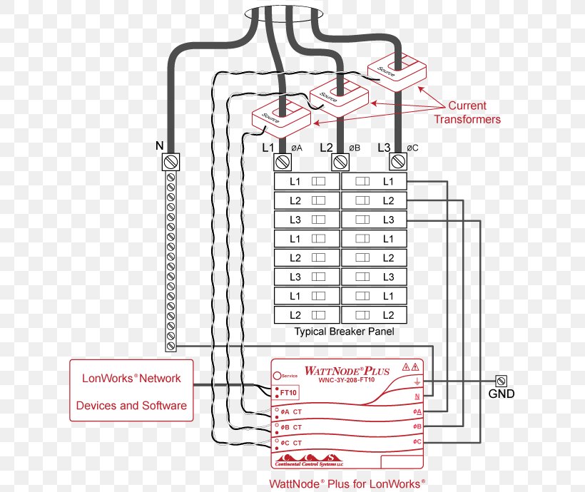
Current Transformer Electricity Meter Wiring Diagram Kilowatt
Transformer electrical diagram. A wiring diagram is a simplified conventional pictorial representation of an electrical circuit. Eatons 2019 revenues were 214 billion and we sell products to customers in more than 175 countries. A more complex example the electrical circuit of an automobile is shown in wiring diagram format in figure 11 and in schematic format in figure 12. Phono cartridge uses mm transformer it converts the movement of the stylus into electrical signal by moving the magnet attached to its tips. Rotating equip and mesh function symbols. Figure 10 provides an example of the relationship between a schematic diagram figure 10a and a wiring diagram figure 10b for an air drying unit.
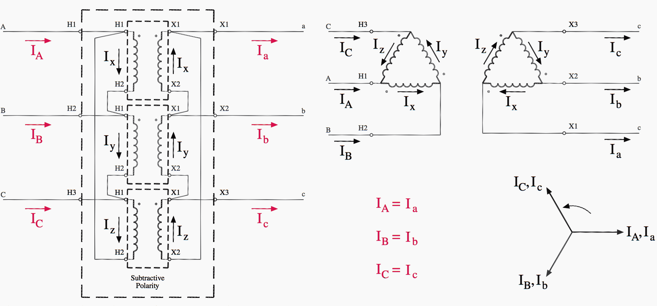
A transformer is a passive electrical device that transfers electrical energy from one electrical circuit to another or multiple circuitsa varying current in any one coil of the transformer produces a varying magnetic flux in the transformers core which induces a varying electromotive force across any other coils wound around the same core. 480v to 240v transformer wiring diagram collections of 480 volt to 120 volt transformer wiring diagram image. The voltage transformer can be thought of as an electrical component rather than an electronic component. Electrical energy can be transferred between. In our industrial control system diagram software you can use the action button to choose the right electrical symbols with one single click. Three phase vector diagrams are commonly used to represent 3 phase transformers are known as transformer vector diagrams.
A transformer basically is very simple static or stationary electro magnetic passive electrical device that works on the principle of faradays law of induction by converting electrical energy from one value to another. A transformer three phase vector diagram is required for determining the fault calculation of an electrical power systempractically almost every electrical power system deals with three phase power. The voltages of a three phase system is shown in the figure below. Besides magnetic circuit and windings it consists of a suitable container for the assembled core and windings such as a tank a suitable medium for insulating the core and windings from its. More electrical symbols switch symbols. Adjustable core transformer such type of transformer has an adjustable core which increases or decreases the flux linkage between the windings to increase or decrease the current flow.
A transformer can not act as a phase changing device and change single phase into three phase or three phase into single phase. 480v 3 phase transformer wiring diagram step down tags to 120v. V l is the line to line voltage and v p is the phase to neutral voltage. We provide sustainable solutions that help our customers effectively manage electrical hydraulic and mechanical power more safely more efficiently and more reliably. To make the transformer connections compatible with three phase supplies we need to connect them together in a particular way to form a three phase transformer configuration.


