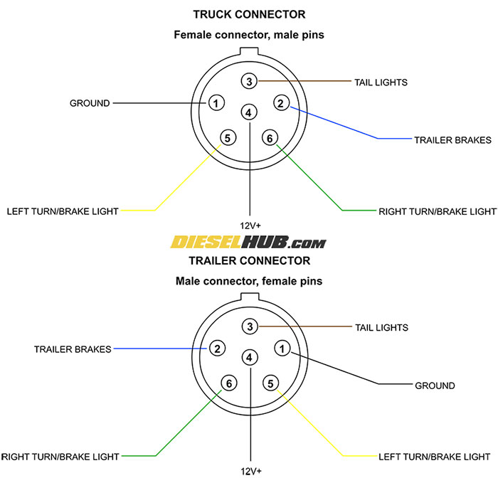
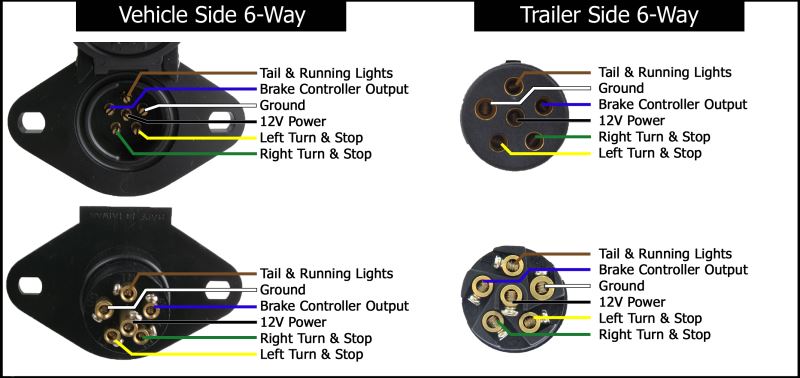
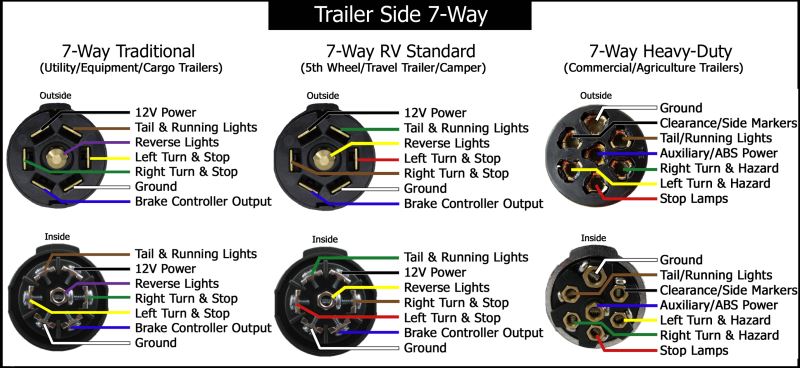
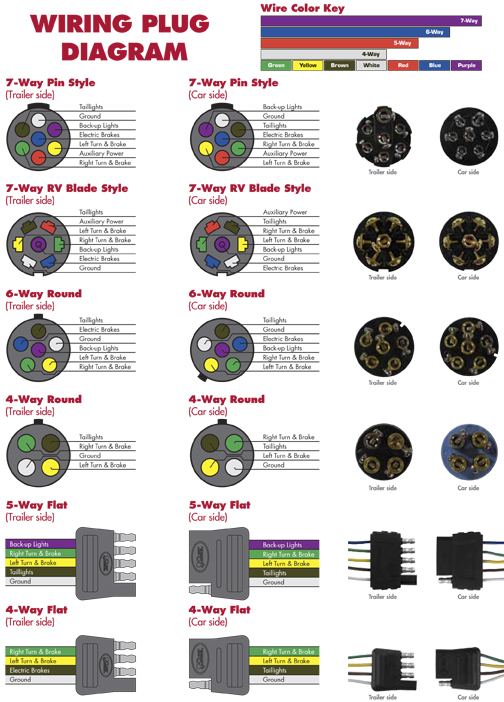
When wiring a trailer connector it is best to wire by function as wire colors can vary. The following trailer wiring diagrams and explanations are a cross between an electrical schematic and wiring on a trailer.

Wiring Diagram 7 Pin Towing Plug 1 Wiring Diagram Source
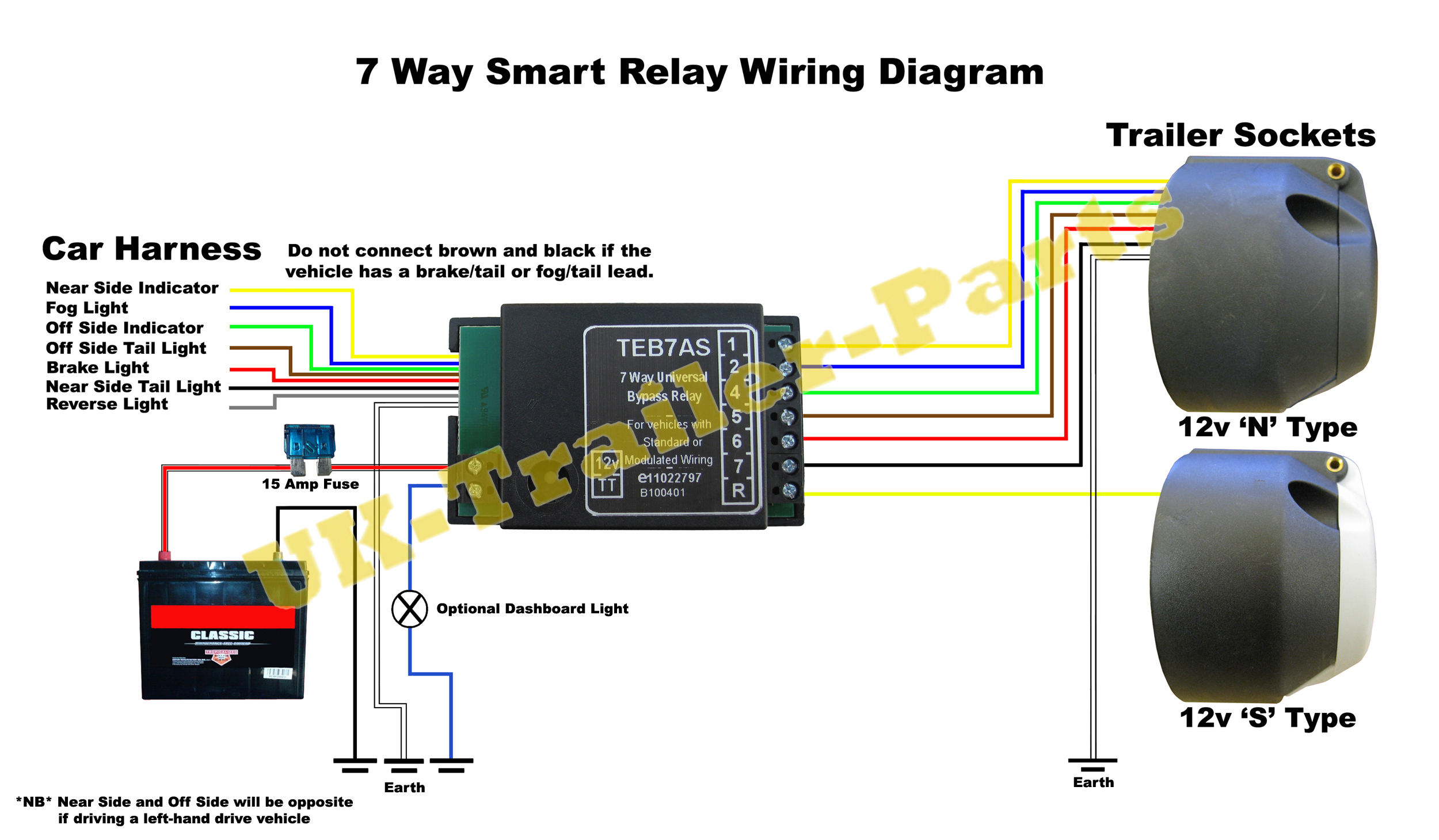
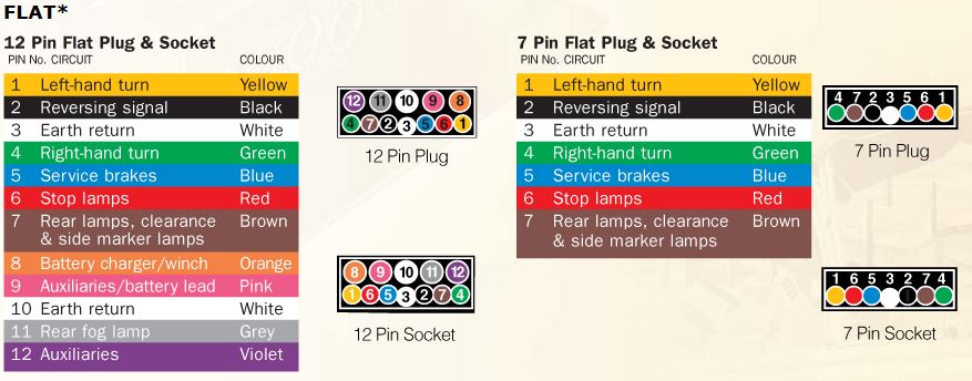
Trailer light socket wiring diagram. The 13 pin version being phased in is newer provides more services than the 7 pin a more positive locking and also better protection against moisture and contamination. Australian trailer plug and socket pinout wiring 7 pin flat and round by daniel bingham heres the wiring diagrams showing the pin out for the plug and socket for the most common circle and rectangle trailer connections in use in australia. 7 way universal bypass relay wiring diagram. 7 pin s type plug and socket wiring diagram. While the basic configuration is a 4 way flat connector that features one female and three male ends you may come across connectors with up to seven pins for additional functions that require wiring including electrically actuated brakes power source for a winch etc. 13 pin euro plug wiring diagram.
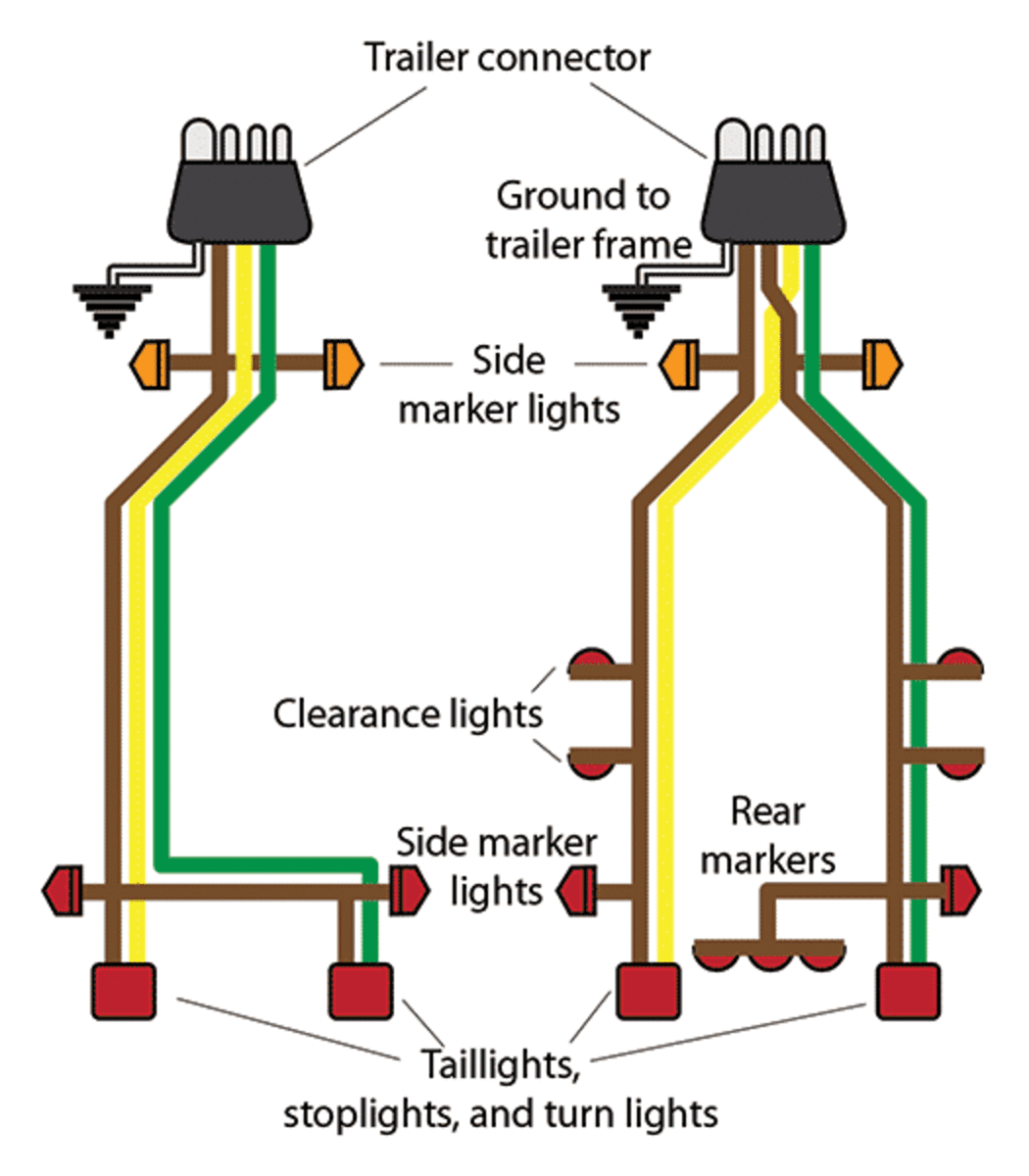
We recommend these standards because they are pretty universal. Other wiring diagrams on this site are listed below. If your vehicle is not equipped with a working trailer wiring harness there are a number of different solutions to provide the perfect fit for your specific vehicle. Trailer connectors between the trailer and passenger car light truck or heavy trucks with 12v systems in europe both 7 pin iso 1724 and 13 pin iso 11446 are common. As the name implies they use four wires to carry out the vital lighting functions. The four wires control the turn signals brake lights and taillights or running lights.
Split charge relay wiring diagram. 4 way trailer connectors are. Lets see what types of connectors the trailer light wiring industry uses today. If you are looking at the inside of the trailer connector where the wires mount to the terminals starting at the top and rotating clockwise. We have an excellent wiring diagram on our website i will provide you a link so you can look at it. That said for specific situations there are industrial standards with different connectors and wire arrangements.
They also provide a wire for a ground connection. The second diagram shows two brake lights two indicators two side lights and a fog light. Click on the image below to enlarge it. Complete with a color coded trailer wiring diagram for each plug type this guide walks through various trailer wiring installation solution including custom wiring splice in wiring and replacement wiring. 4 way trailer connectors are typically used on small trailers such as boat snowmobile utility and other trailers that that do not use brakes.


