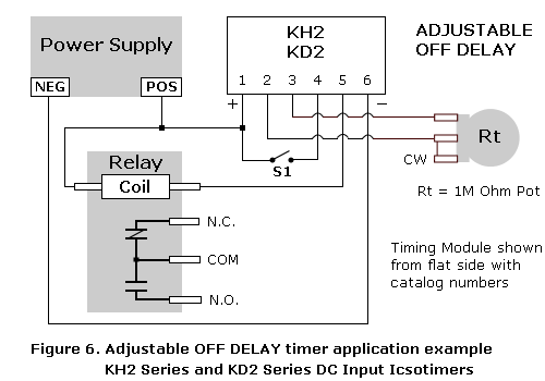
On delay timer circuit diagram wiring diagram contactor with push button circuit diagram of delay timer on off power off delay timer circuit diagram 2 way lighting circuit triggering transformer push button fan switch light activated switch circuit diagram wd081 text. Wiring diagram for bathroom fan simple wiring bathroom fan light.
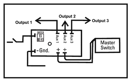
Mzl Fd 12v Ignition Sensing Delay Timer Acdc Industries
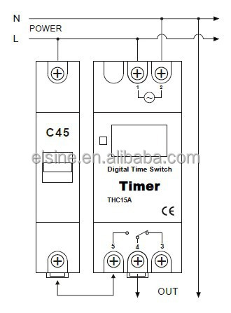
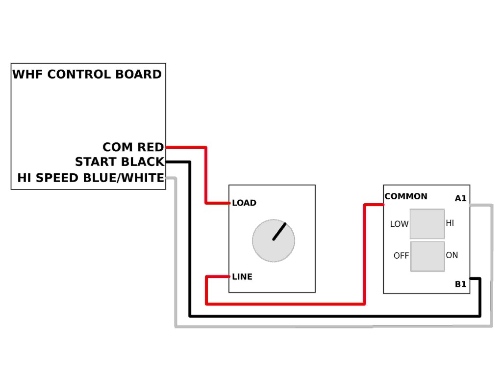
Timer switch diagram. The best thank you for me is to subscribe to my channel and thumb. Leviton 500 watt 60 minute in wall digital timer model r62 6161t 1lw 21 78 21 78. Consult your timers wiring diagram to ensure which wire is the hot lead from the switch. Home automation and light switch wiring electrical question. This video is about 12v dc timer model cn101a sold on ebay and amazon. Wiring diagram for bathroom fan 2019 heller exhaust fan wiring.
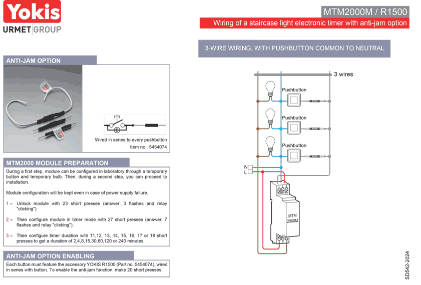
Simple wiring diagram for bathroom fan with timer. Then connect the switched wire typically a blue wire to the black wire leading to the device. Set your store to see local availability add to cart. Digital timer switch setting with wiring for. This a great home automation project. Defiant 15 amp 4 hour in wall push button countdown timer switch with screw terminals white model 30469 24 98 24 98.
Display delay timer module can be programmed 01 seconds to 999 seconds 17 minutes. Arduino adjustable timer is simple circuit to generate timer for required time. Bathroom fan with timer wiring diagram collections of bathroom fan with timer wiring diagram collection. The timer keeps zeroing out to the flashing initial setup screen after about 5 or 6 toggles of the other light switch in the box. Im trying to replace a single pole light switch with a timer light switch in a box that also has another single pole switch going to another light. Free delivery with 45 order.
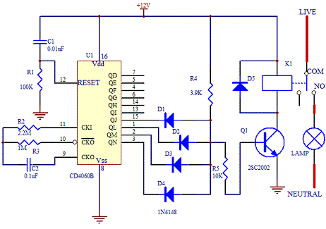
How to setup 12v dc timer with wiring diagram cn101a scott wilson. Here a relay is used to switch the load for certain amount of time. The red and black are used for hot and the white neutral wire at the switch box allows for powering a timer remote control or other programmable switch. This is used to switch on the loads for the certain time period and then they are automatically switched off. Each component should be placed and linked to other parts in particular manner. Free delivery with 45 order.
Here arduino plays a key role in setting this time period. Because the electrical code as of the 2011 nec update requires a neutral wire in most new switch boxes a 3 wire cable runs between the light and switch. This is an updated version of the first arrangement. Although its sometimes confused with a timer switcha device that simply turns off a device such as a light fixture or vent fan after a prescribed amount of running timea time switch serves a different functiontime switches essentially keep track of the time of day and turn power on and off at whatever times are desired by the user.
