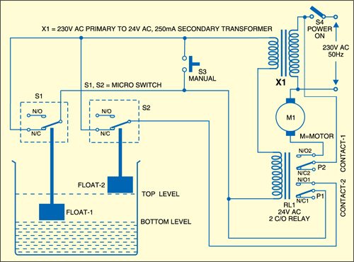
Automatic water level controller circuit. Also read automatic water pump controller without ic.
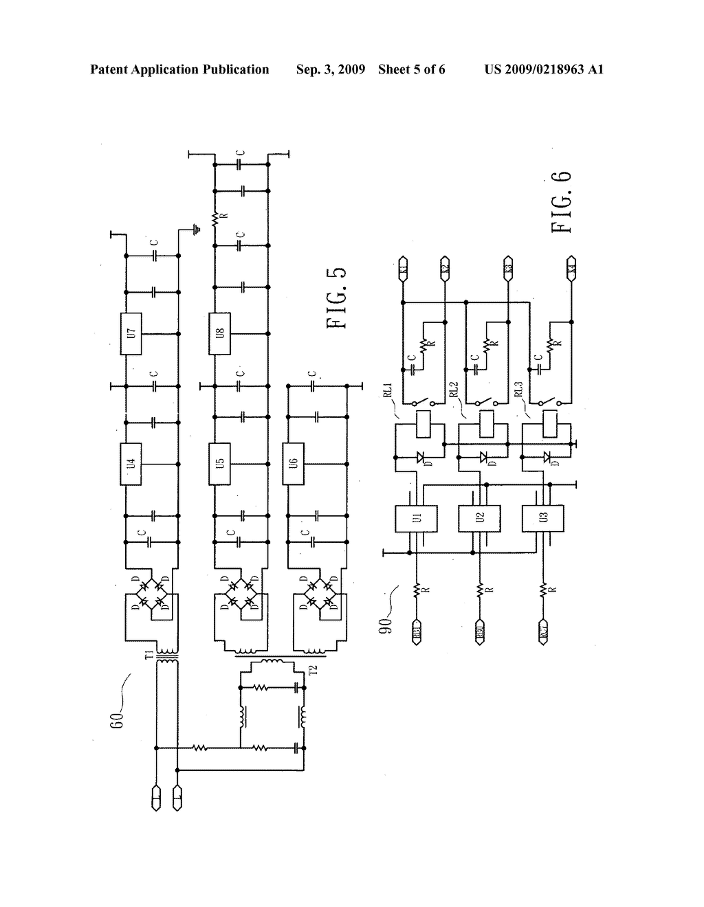
Linear Motor Automatic Control Circuit Assembly For
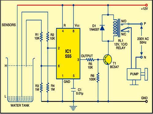
Automatic pump control circuit diagram. It works off a 12v dc power supply and consumes very little power. The switch is shown as a single pole. This is a very useful circuit for household water tank. Hello friends today in this video i have shown how to make a simple automatic water pump controller circuit. Automatic pump controller using 555 timer. The water level is sensed by two floats to operate the switches for controlling the pump motor.
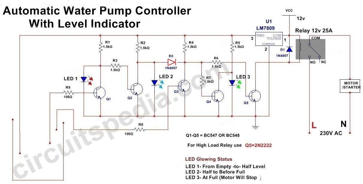
The circuit will automatically switch on any water pump motor when the level of water in a tank reaches below from the required level and automatically switch off the pump after filling the tank. Here is a very useful project of an automatic water pump controller circuit. Its very simple too. In the countryside water is very important. Automatic water pump control circuit help to control water tank overflow. Connect the circuit diagram as shown in fig and use dc power supply by battery or adaptor to operate this circuit.
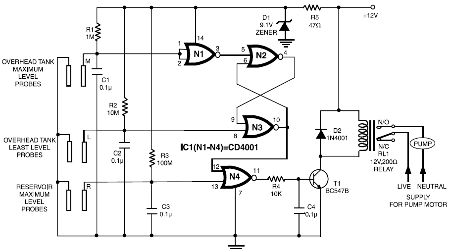
This project also work for save water and save electricity. You can use up. It can automatically switch on and off the domestic water pump set depending on the tank water level. Built around only one nand gate ic the circuit is simple compact and economical. This is an automatic water pump controller circuit diagram using an ne555 timer. Two wires positioned as a sensor one at the bottom level of the tank and one is the upper top level where required to before overflow.
Controller circuit and indicator circuit. Hand off automatic controls are used to permit an operator to select between automatic or manual operation of a motor. The circuit shown in figure 271 permits a motor to be operated by a float switch or to be run manually. Automatic water level controller circuit is a simple engineering project. Hand off automatic controls recognize hand off automatic switches on a schematic diagram. The most to use the groundwater to dig as a pond and for the convenience.
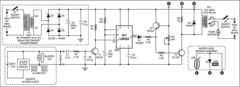
The circuit can be divided into two parts. But waste a lot of electricity. This circuit works well with 12v dc power. This project is environmental related project. Here is a simple automatic water level controller for overhead tanks that switches onoff the pump motor when water in the tank goes belowabove the minimummaximum level. The shorter steel rod is the water high sensor whereas the longer is the water low sensor.
They often use the pump automatically. Automatic water pump controller circuit. 1 shows the controller circuit. By means of a relay employed to drive a water pump this circuit provides automatic level control of a water reservoir or well. You can implement this motor driver circuit at your home or college using less costly components. Water reservoir automatic level control simple circuitry 12v supply.


