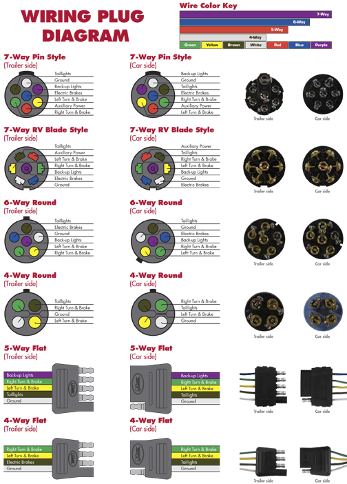
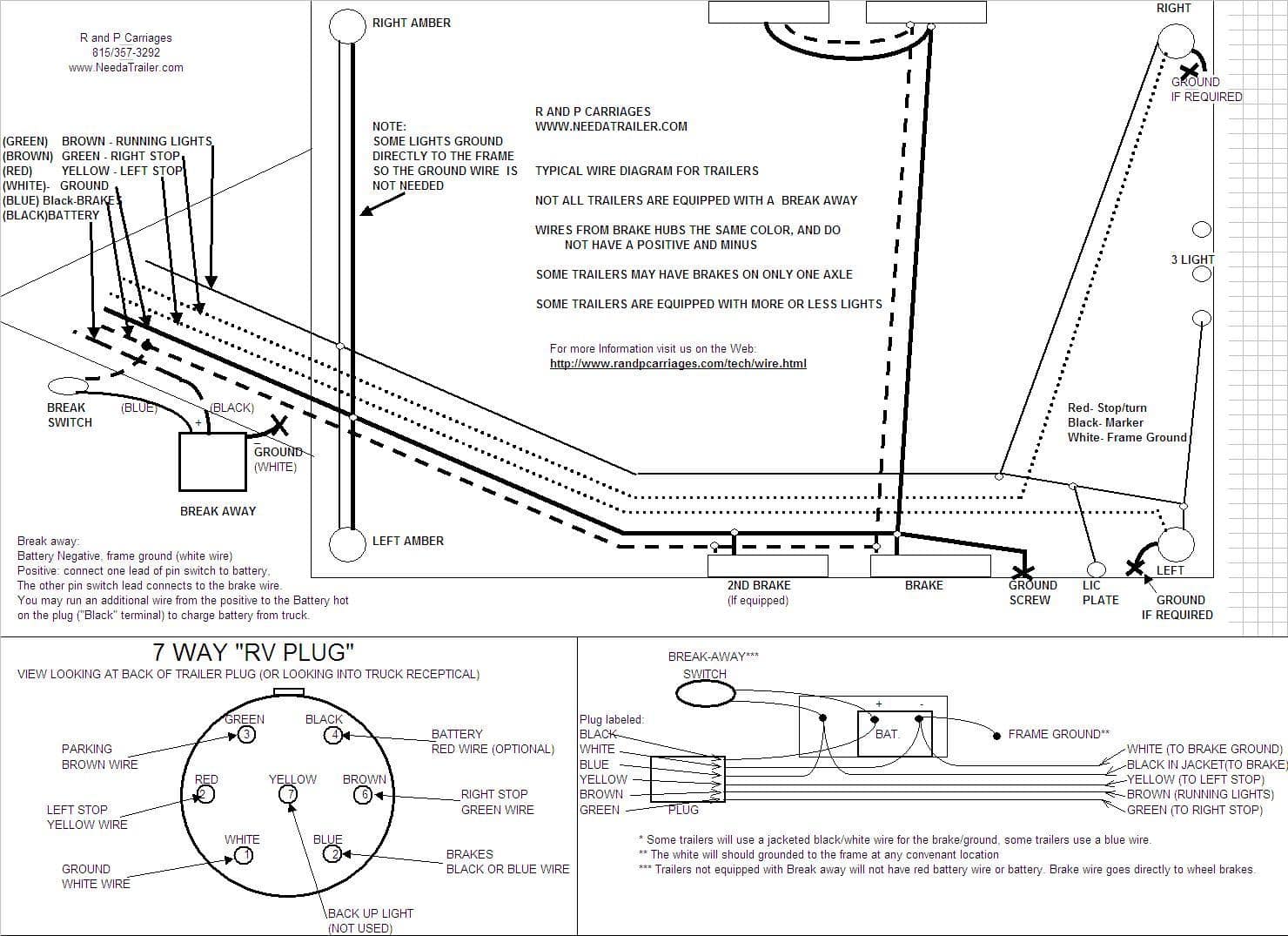
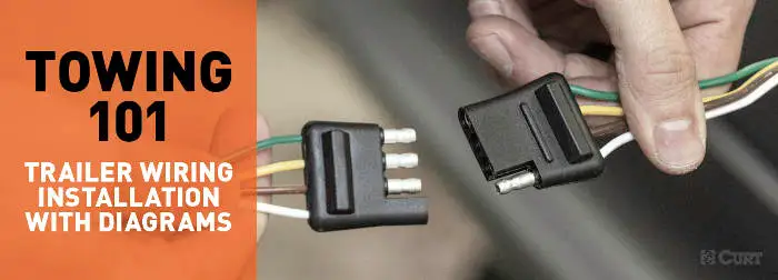
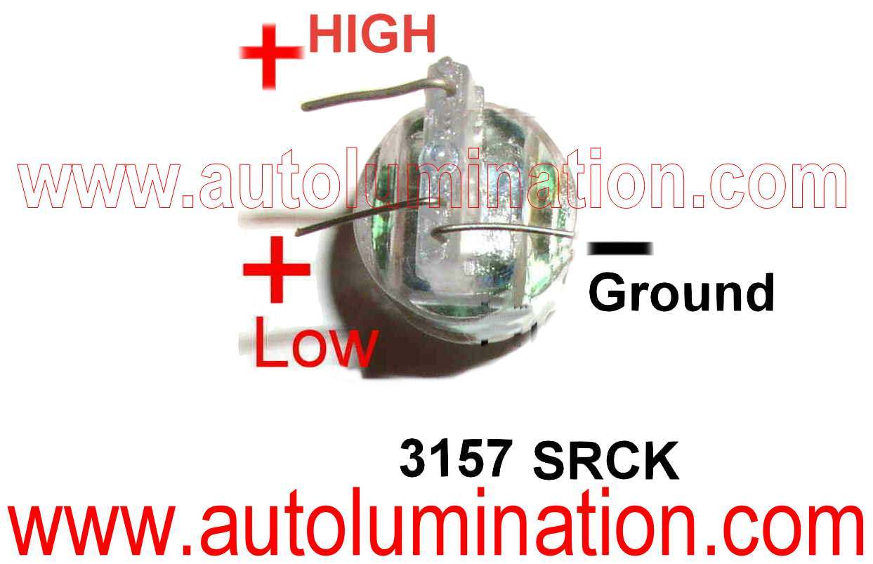
The bulb lights when a circuit is good. Various connectors are available from four to seven pins that allow for the transfer of power for the lighting as well as auxiliary functions such as an electric trailer brake controller backup lights or a 12v power supply for a winch or interior trailer lights.
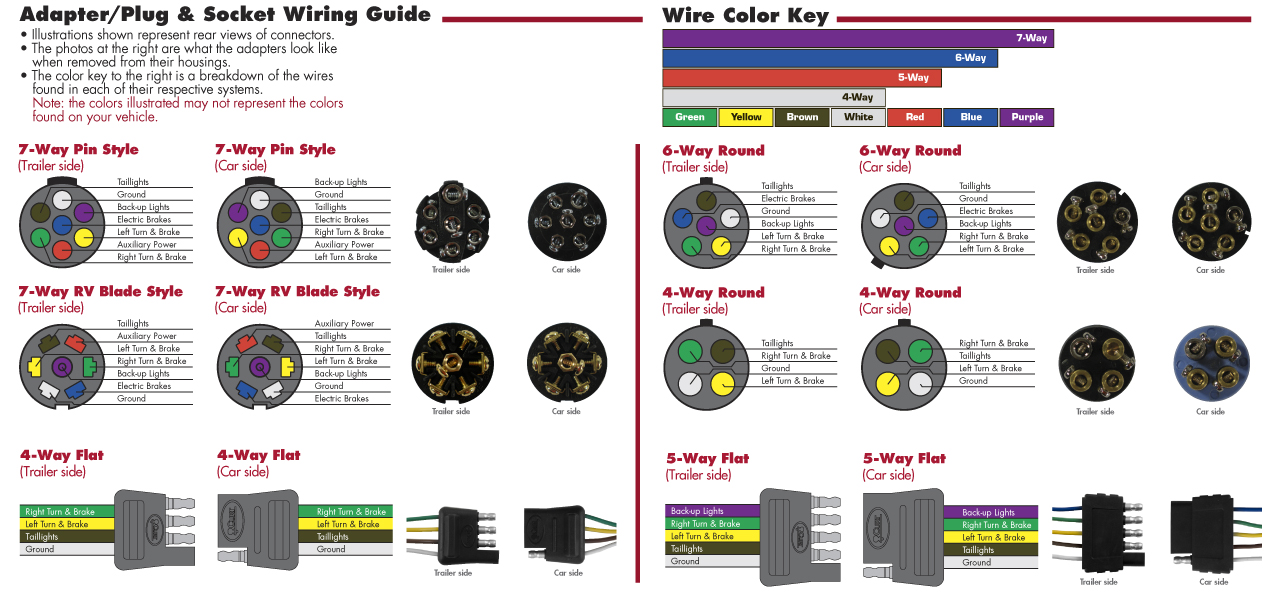
Pollak Trailer Plugs Wiring Diagram H1 Wiring Diagram
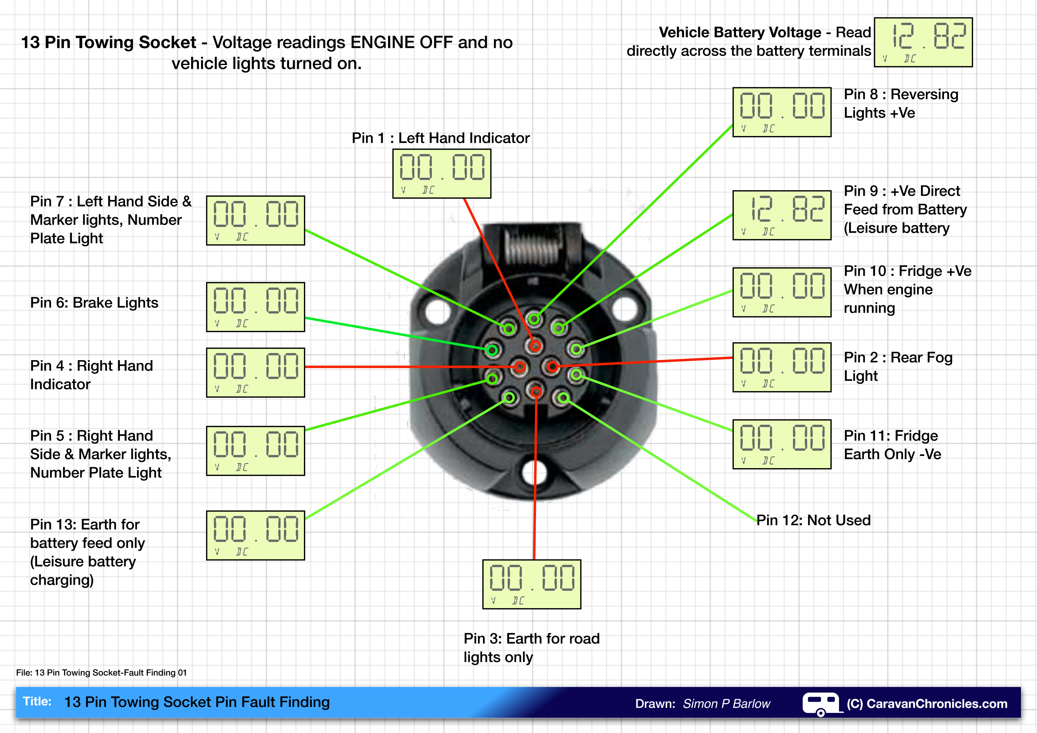
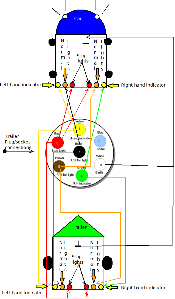
Trailer light socket diagram. This supplies power to the road lighting of your trailer or caravan. If your truck has a built in 7 pin socket but you only need 5 of the pins. This has now been replaced by 13 pin euro plugs on all new caravans. Uk trailer wiring part 2 lights and 7 pin socket duration. This is the standard uk wiring of a the normal socket and plug otherwise known as 12n. Trailer wiring diagrams trailer wiring connectors.
This means that when you apply the brakes or switch on the signals the lights of the trailer should mirror these signals. Close up of a continuity tester. The basic purpose remains the same whether your truck and trailer is using a 4 way 5 way 6 way or 7 way connector. If you are rewiring your trailer completely check out our trailer rewiring guide. Wiring diagrams 27976 views. The diagram below shows the view from outside the vehicle socket under the flap and from inside the trailer or caravan plug.
Lets see what types of connectors the trailer light wiring industry uses today. Removing a trailer hitch ball. By law trailer lighting must be connected into the tow vehicles wiring system to provide trailer running lights turn signals and brake lights. In the trailer wiring diagram and connector application chart below use the first 5 pins and ignore the rest. Trailer electrical connectors come in a variety of shapes and sizes. Connect the jumper wire to one of the pins in the trailer socket.
A continuity tester contains a light bulb and a battery. Use the 7 pin connector anyway see below and just leave out the last 2 wires. When you buy a trailer the on board power supply should be connected to the vehicles via a plug or socket. Plugs trailer side and sockets vehicle side are available in all standard formats and can be spliced into your existing tow wiring. Below is a diagram for the original plug and socket showing the functions of each pin. While the basic configuration is a 4 way flat connector that features one female and three male ends you may come across connectors with up to seven pins for additional functions that require wiring including electrically actuated brakes power source for a winch etc.
7 pin trailer wiring diagram harness duration. The 7 pin n type plug and socket is still the most common connector for towing. Find the trailer light wiring diagram below that corresponds to your existing configuration. Modern cars use a converter for this. This helps you to communicate with other drivers wherever you are going.

