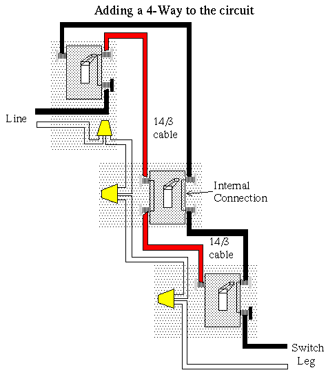
This is the wiring for a dimmer in a 4 way circuit. As you will see most 4 way switch wiring is placed between the wiring of two 3 way switches therefore a 4way switch is installed with two 3way.

Wiring Diagram 3 Way Timer Switch Wiring Diagram
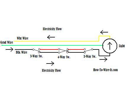
Three way four way switch wiring diagram. The white wire between switches is not being used as a neutral. There are really only two basic four way switch wiring methods. Lets start wiring a four way switch. In the above diagram the white wire must be re identified as a hot wire at each switch location. The diagram below is based on the video you watched above. In order for 4 way switches to work they must be installed between two 3 way switches by 143 wire.
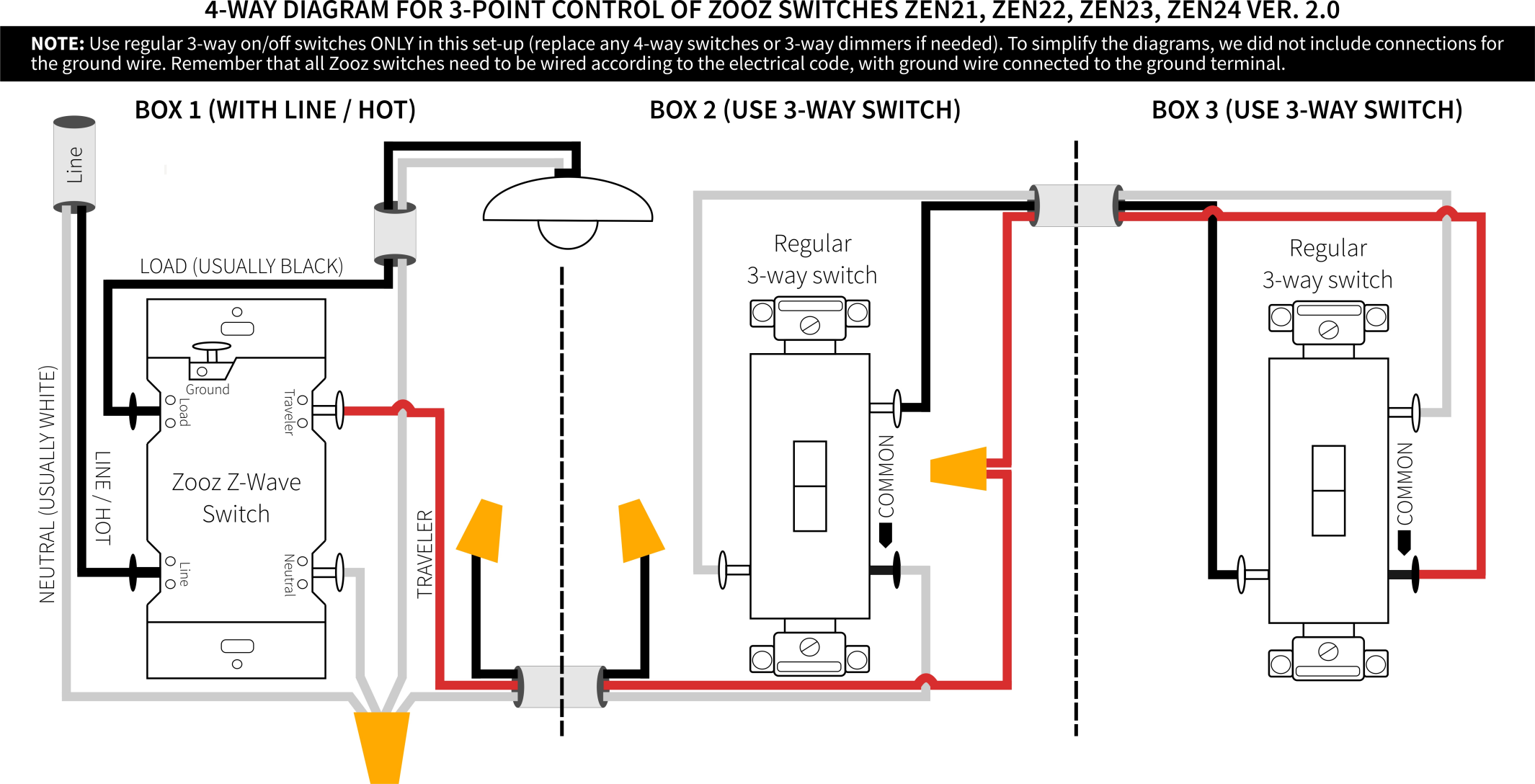
With these diagrams below it will take the guess work out of wiring. Pick the diagram that is most like the scenario you are in and see if you can wire your switch. Each pair of traveler terminals should be wired to the traveler wires from one of the 3 way switches in the circuit. 3 way and 4 way occupancy sensors for indoor motion detector applications electrical question. Take a closer look at a 3 way switch wiring diagram. The black screw on a 3 way switch diagram is for the continuous hot wire that comes from the circuit.
If more than three switches are needed simply place more 4 way switches between the three way switches. 3 way switch wiring diagram. This might seem intimidating but it does not have to be. How do i wire a motion a sensor to control lights. 3 way switch wiring diagram with line and load in the same switch box. An example of three way switch wiring with the line and load in the same 4 square electrical box.
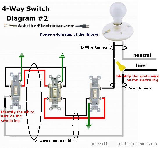
A four way switch allows the traveller wire from one switch to travel through or criss cross between another switch. Three wire cable runs between all the switches and 2 wire cable runs to the light. With a pair of 3 way switches either can make or break the connection that completes the circuit to the light. To make this circuit work a 3 way dimmer can be used in place of one or both of the standard 3 way switches. I have a three family home unit and in the common stairwell i have a 3 way switch on the first floor a 4 way switch on the second floor and a 3 way switch on the 3rd floor which are all controlling the common stairway lighting. A 3 way switch wiring diagram is a simple drawing showing how to connect the wires to each of the four screws on the 3 way switch.
A 4 way switch must be wired between two 3 way switches as shown in the diagrams on this page. What is the black screw for on a 3 way switch diagram. 4 way dimmer switch wiring diagram. Wiring a 3 way light switch is certainly more complicated than that of the more common single pole switch but you can figure it out if you follow our 3 way switch wiring diagram. 4 way switch wiring 4 way switches provide switching from three or more locations. Wiring a 3 way light switch.
One ground and 4 circuit terminals divided into two matching pairs called travelers. In the diagrams below the first switch 3 way common terminal connects to line voltage. A four switch configuration will have two 3 way switches one on each end and two 4 way switches in the middle. A 4 way switch has five terminals. The first switch 3 way travelers brass color connect to one pair of the second switch 4 way travelers black or brass color.
Gallery of Three Way Four Way Switch Wiring Diagram