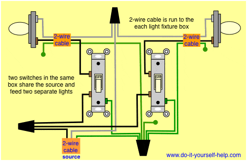
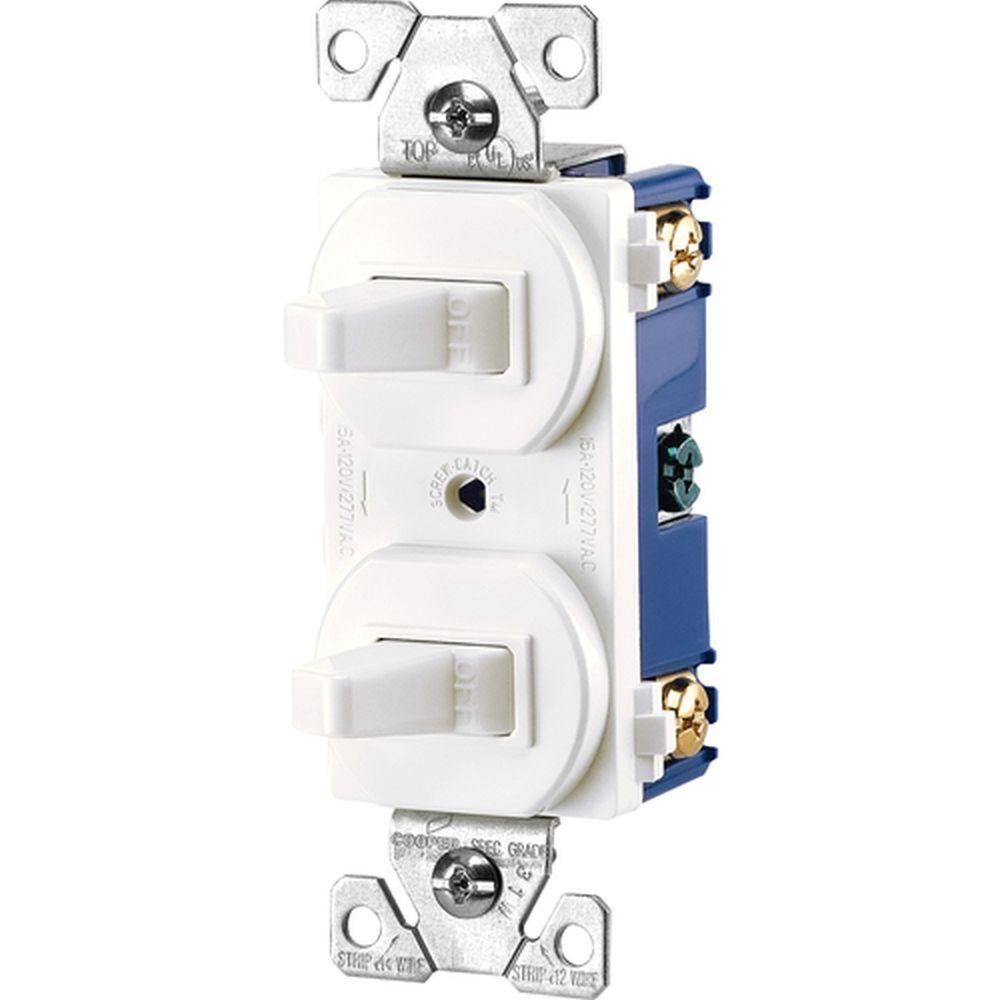
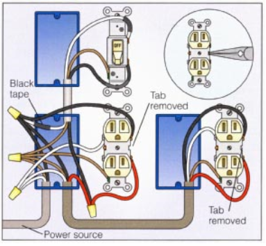
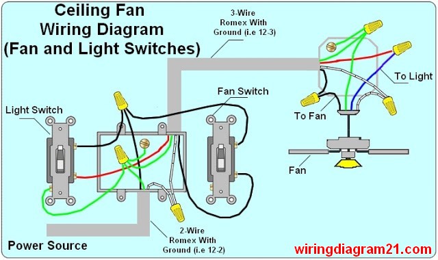
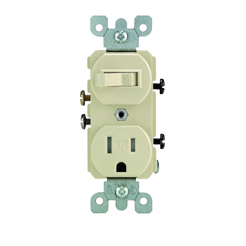
Electrical wiring for a switch outlet combination. This repeats until the end of the chain.

Wiring A Double Outlet Diagram Wiring Diagrams
Wiring diagram for double outlet. Any break or malfunction in one outlet will cause all the other outlets to fail. I will show how to wire a double receptacle this is the main reason i have not insulated or dry walled my shop yet. This wiring allows the electricity to continue from the receptacle on to any other outlets in the circuit and it provides a switch for controlling a light fixture or other load such as another wall outlet or a ceiling fan. This is how i added a couple of outlets to my shop. The outlet addition methods we show here are based on the most common wiring 14 gauge wire on a 15 amp circuit and an 18 cu in. Wiring them on the same circuit requires jumper wires.
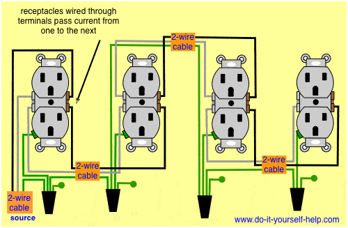
Use the needle nose pliers to create a hook in the piece of bare copper wire that will be used to ground the new double outlet as well. Wiring diagram for dual outlets. How to install electrical outlet and switch combo wiring in most cases the primary power source is shared between the switch and the outlet either with a wire jumper or the bridge or tab that is located on the side of the combo switch and outlet. In the diagram below a 2 wire nm cable supplies line voltage from the electrical panel to the first receptacle outlet box. Box typical inside dimensions are about 2 in. Just hold it near any wire or cable to see if its energized.
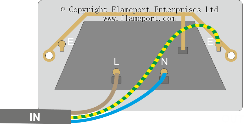
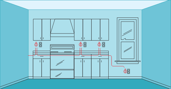
There are two ways to wire a double gang outlet which is two duplex receptacles together in a double gang outlet box. This wiring is commonly used in a 20 amp kitchen circuit where two appliance feeds are needed such as for a refrigerator and a microwave in the same location. Wiring a combo switch outlet. The black wire line and white neutral connect to the receptacle terminals and another 2 wire nm that travels to the next receptacle. The second way wiring them on separate circuits requires two live cables. Here 3 wire cable is run from a double pole circuit breaker providing an independent 120 volts to two sets of multiple outlets.
The neutral wire from the circuit is shared by both sets. This is also known as a quad receptacle. Just plug it into any gfci outlet and the lights will indicate whether the outlet is properly wired. Use a noncontact voltage tester like this to double check that all wires in a box are dead after turning off the circuit breaker. This diagram illustrates a switch and receptacle in the same outlet box located in the middle of the circuit. Step 3 install first outlet receptacle after you have prepared the wiring in the junction box install the first outlet by securing the black wire to the screw terminal with the brass colored screw.
For wiring in series the terminal screws are the means for passing voltage from one receptacle to another. Multiple outlet in serie wiring diagram. This type of work should.

