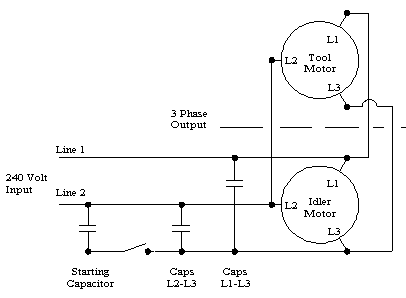
The purpose is the same. Here are 3 popular options.
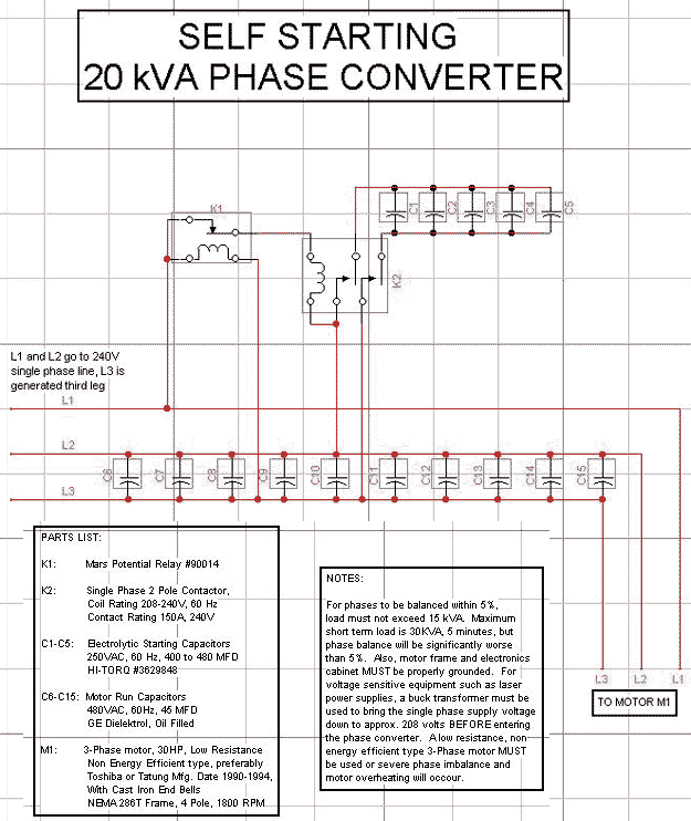
Laser Hobbyists Hobby Archives Www Laserfx Com
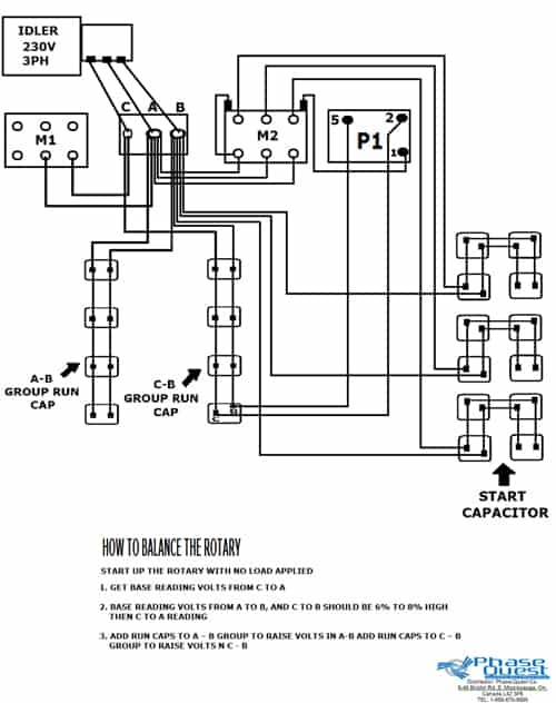
Three phase converter wiring diagram. It reveals the elements of the circuit as streamlined forms and also the power as well as signal connections between the devices. The converter is a machine about the size of a 10 gallon water cooler. Our three phase converters are ac single to three phase 208v 220v 240v 440v 460v and 480v converters. Literally a circuit is the path that enables. Always have phase converter on before starting any 3 phase load. If you need a different configuration just let us know.
Obtaining from point a to direct b. A very first appearance at a circuit diagram may be confusing yet if you could check out a subway map you could check out schematics. How to build a diy rotary phase converter. 3 inside three phase converter wiring diagram rotary wiring a novice s overview of circuit diagrams. A wiring diagram is a streamlined standard photographic depiction of an electrical circuit. Our phase converters are built to last using the highest quality standards and only the highest quality components.
Phase converter must be new same size have the same features and quality. If you are reading this then it is most likely because you have acquired or are thinking about getting a piece of decommissioned industrial shop equipment that is powered by a 3 phase motor but your shop only has single phase power. All wiring must be done by a licensed. You have several options wiring to your loads. All power to and from the converter is hard wired meaning no electrical sockets the three phase converter will come with a wiring schematic for properly connecting the black red blue and neutral white lines to the junction box. 3 phase machinery 3 phase machinery 230 volt three phase panel off on note.
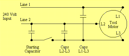
Lastly complete the switch assembly and screw down the cover. If you have any questions about our policies guaranties or products please call our 247 toll free line 1 602 640 0930. Contactor c1 has replaced the drum switch and contactor c2 has replaced the momentary pushbutton for connecting the starting capacitor between l2 and l3. If you look closely you will see all the basic elements from the very simple static phase converter diagram shown earlier. For a typical 1 horsepower 230 volt three phase motor to work well on single phase you will need two ac motor run capacitors c1 and c2 of around 10 micro farads each and preferably with at least a 300 vac rating however a higher voltage capacitor works the same. North american phase converter offers a large selection of all of these items.
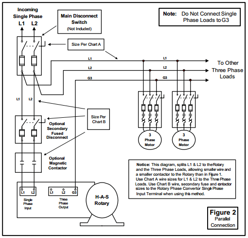
Above is the field or power wiring diagram. Up to 3 times the converters hp may be run in this configuration see page 5 for specs. All wiring must be done by a licensed electrician. 3 phase converter wiring electrical load centers electrical disconnect switches and twist lock phase converter plugs and outlets. Collection of american rotary phase converter wiring diagram.


