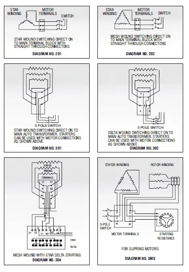
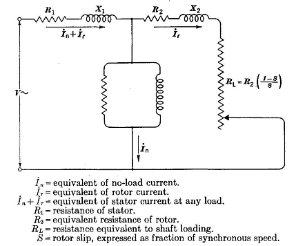
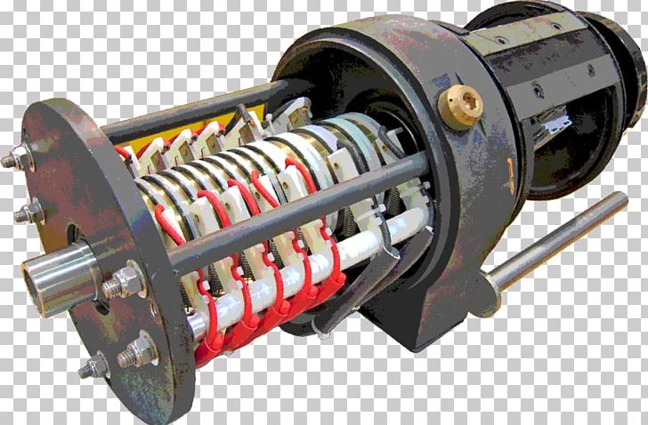
For ease of understanding instead of the current 24 slots winding lets use a 12 slot winding. Slip rings how does a ring work powerbyproxi wireless.
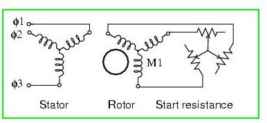
Starting Of Slip Ring Induction Motor Explained In An Easy
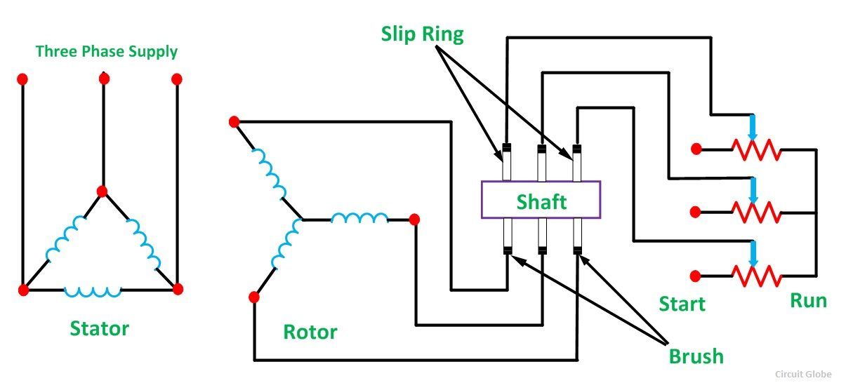
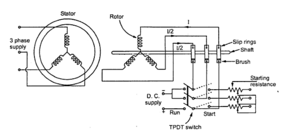
Slip ring motor wiring diagram. High voltage slip ring motor high voltage wound rotor motor wound rotor motor slip ring motor. Instead of bars in this motor three windings are used. In the induction motors used in lift and hoists you will see a type of rotor called a slip ring rotor whereas in most of. Adjusting the resistance allows control of the speedtorque characteristic of the motor. You may also read. Three phase motor control installation wiring diagrams.
The stator circuit is rated as same in the squirrel cage motor but the rotor is rated in frame voltage or short circuit current. A simple circuit diagram of contactor with three phase motor. Induction motors have been ruling the industrial world for many decades. Three phase motor power control wiring diagrams 3 phase motor power control wiring diagrams three phase motor connection schematic power and control. However the rotor construction of the slip ring motor is quite interesting. As the motor accelerates.
Yrkk series medium size high voltage 3 phase asynchronous slip ring wound rotors are used to drive windlass press machinery crusher stock removing drawbenchs and other general purpose machinery. A slip ring is an electromechanical device that allows the transmission of power and electrical signals from a stationary to a rotating structure. Lets see how the slip ring rotor does it. Three phase slip ring rotor starter control power diagrams 3 phase slip ring rotor starter control power diagrams slip ring rotor power and control. A slip ring can be used in any electromechanical system that requires rotation while transmitting power or signals. Spare parts sirus electronet india pvt ltd exploded view of slip ring alternator.
This construction of the rotor is aimed at reducing the phase difference. It can improve mechanical performance simplify system operation and eliminate damage prone wires dangling from movable joints. The frame voltage is the open circuit voltage when the rotor is not rotating and gives the measure of turns. A wound rotor motor also known as slip ring rotor motor is a type of induction motor where the rotor windings are connected through slip rings to external resistance. Wound rotor motors can be started with low inrush current by inserting high resistance into the rotor circuit. Slip rings how does a ring work powerbyproxi wireless.
Three phase slip ring rotor starter control power diagrams. Power and control wiring diagrams. The slip ring induction motor could be used for industrial wires where variable speed and high starting torque are prime requirements. The stator of slip ring induction motor is very much the same as that of the squirrel cage induction motor but the construction of its rotor is very much differentstator winding can be either star or delta connected depending upon the design. Automatic ups inverter wiring connection diagram to the home. The slip ring induction motor has two distinctly separate parts one is the stator and other is the rotor.
Check more diagrams here. Component slip ring motor ac buy ringac starter for sale pricechina manufacturer download induction sjr kw st.

