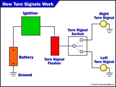
The turn signal circuit gets power when the ignition key is on. The rest you can ignore.

Installing Turn Signals Electricity Electrical Wiring
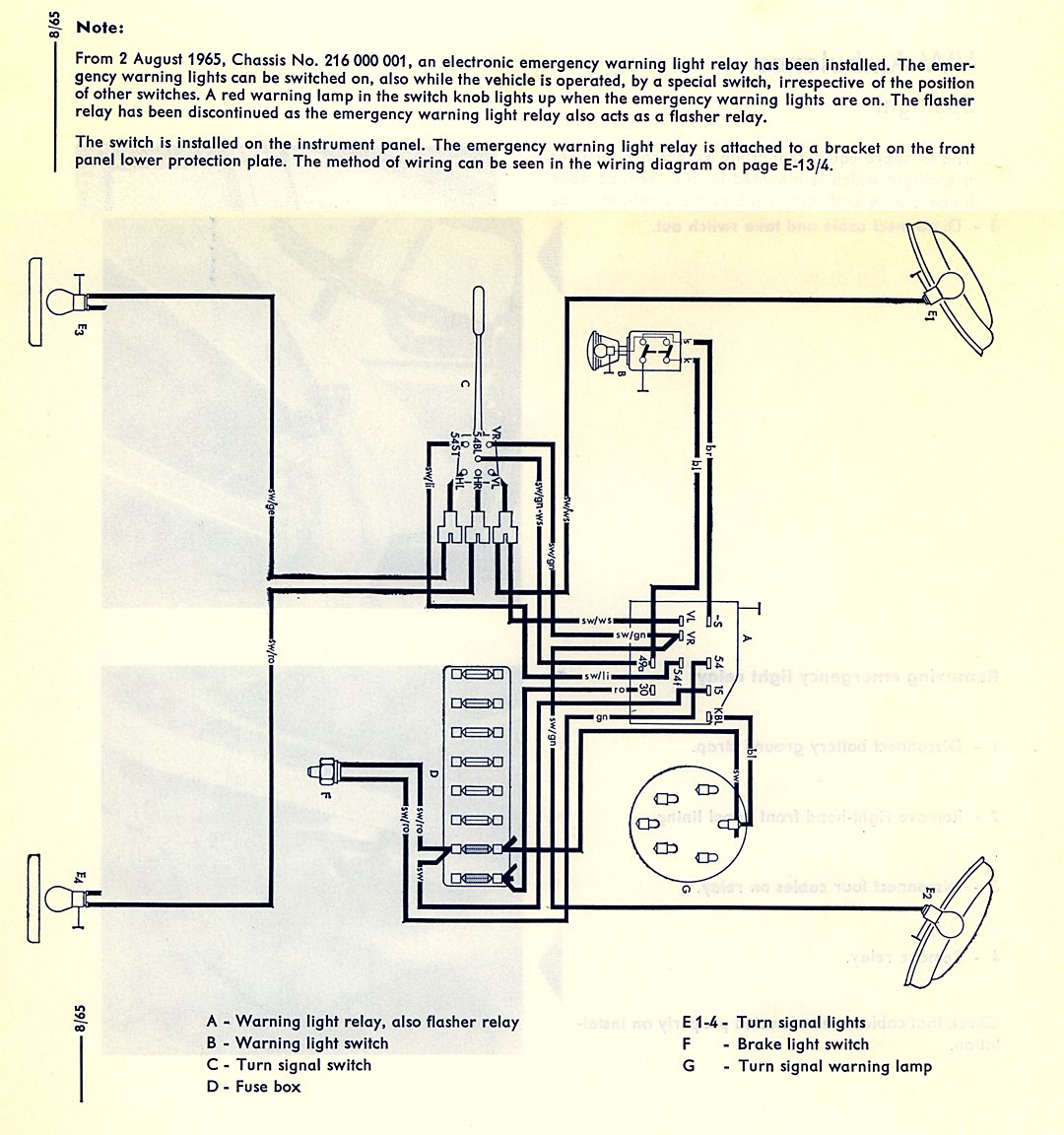
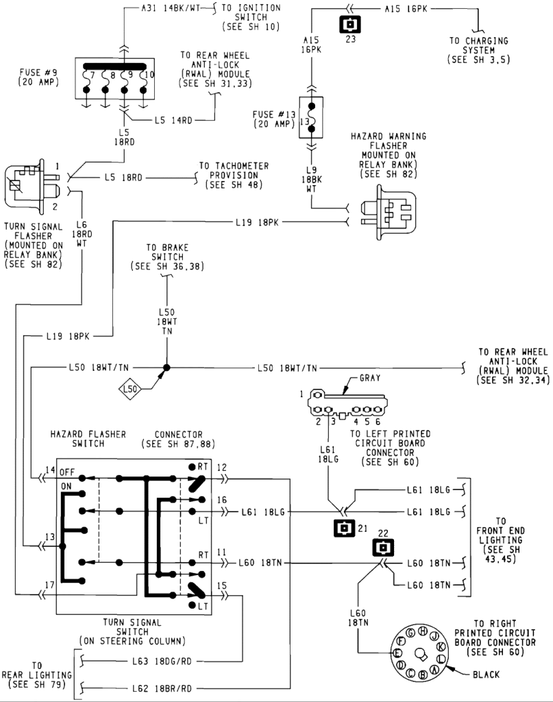
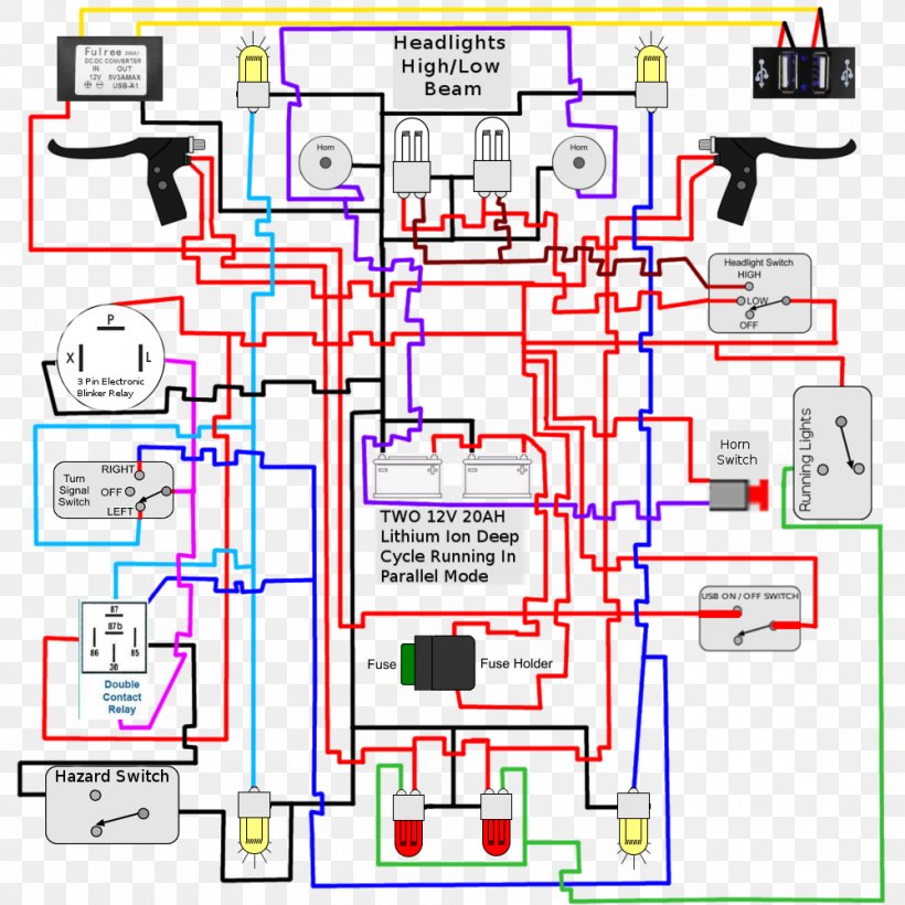
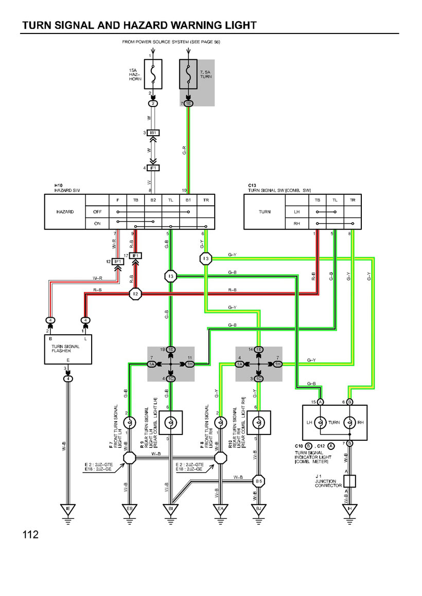
Signal light wiring diagram. 14 turn light flasher what makes it click tubalcain duration. Turn signal flasher wiring diagram led turn signal flasher wiring diagram motorcycle turn signal flasher wiring diagram turn signal flasher circuit diagram every electric arrangement consists of various unique parts. The 4 pin connector only has the first 4 items listed. Wiring diagram signal light and hazard light duration. If not the structure wont work as it ought to be. The converters arent made to run the extra voltage.
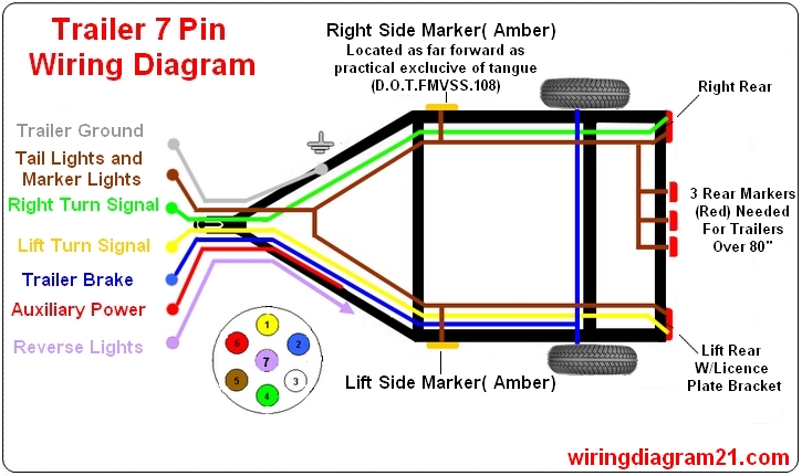
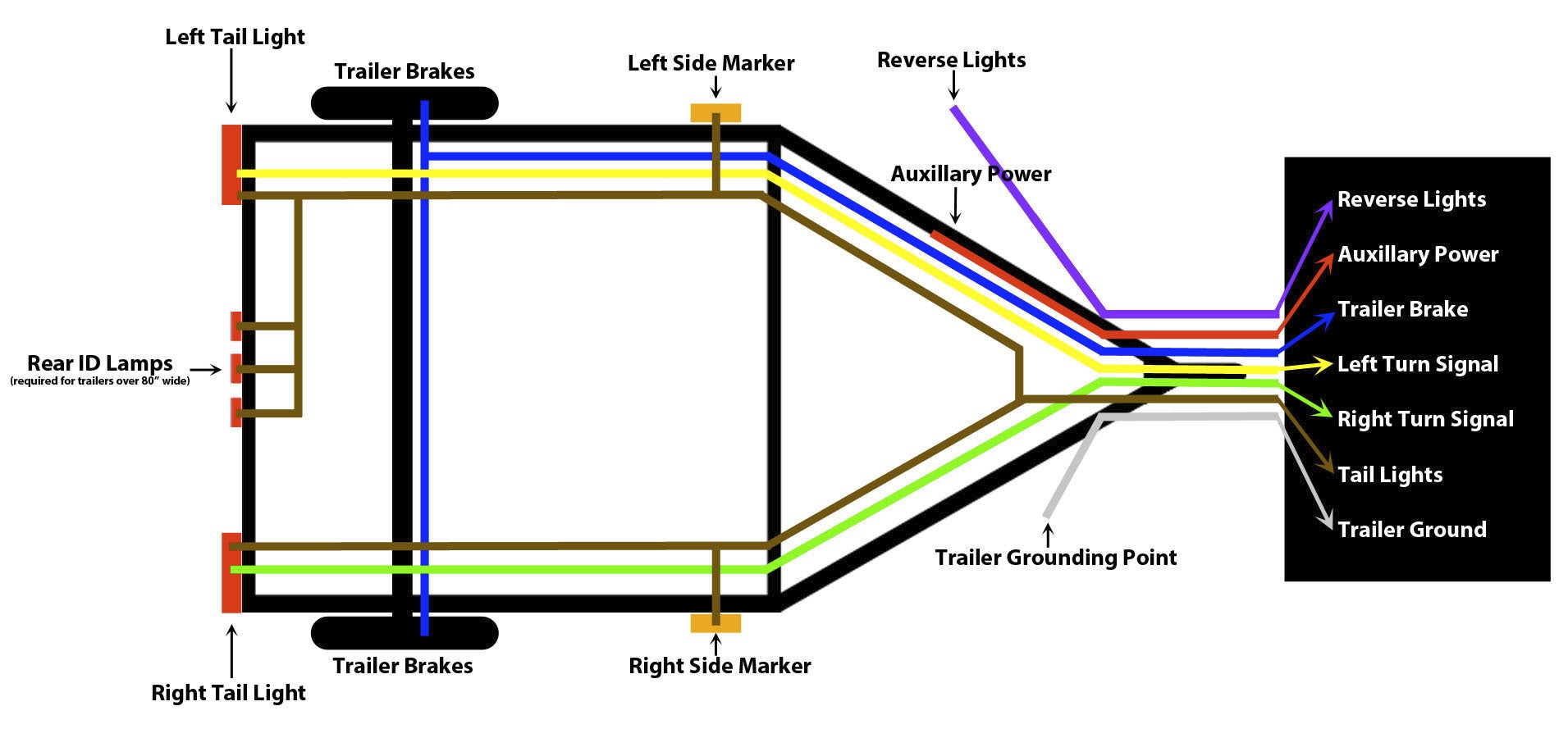
What makes it work. A wiring diagram is a streamlined standard pictorial depiction of an electric circuit. It shows the parts of the circuit as simplified forms and also the power and also signal links in between the devices. Please see the trailer wiring diagram and connector application chart below. Each part should be placed and linked to other parts in specific way. It doesnt make any difference as the tail light wiring isnt affected.
Variety of universal turn signal wiring diagram. From there it goes to the stalk on the steering column. Lets take a look at how the turn signal circuit is hooked up. Motofix ph 100211 views. Green right turn signal right brake light. All youre worried about is the brake and turn signal wires.
Dont try to run them with leds. Some have the tail light wire running through them 4 wire into 3 wire and some dont 3 wire into 2 wire. The power goes through a fuse panel into the thermal flasher. Yellow left turn signal left brake light 4.
