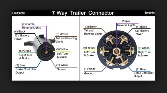
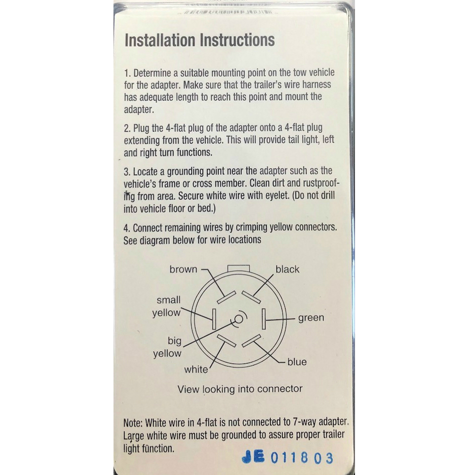
The basic purpose remains the same whether your truck and trailer is using a 4 way 5 way 6 way or 7 way connector. If not the arrangement will not function as it ought to be.

Trailer Electrical Wiring Diagram H1 Wiring Diagram
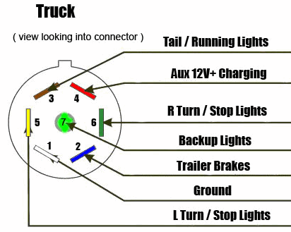
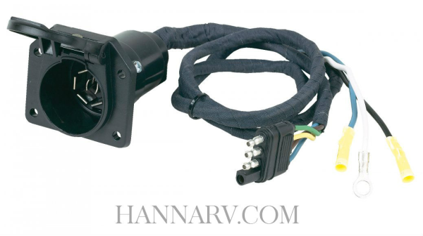
Wiring diagram for trailer lights 7 way. 7 way connectors allow for all functions provided by 6 way connectors three basic lighting functions electric brakes and additional power supply with the seventh wire for backup lights. This universal wiring kit lets you install an electric brake controller sold separately in your vehicle and a 7 way connector for your trailer lights at the same time. Some trailer builders just connect this wire to the frame then connect the ground from all the other lights and accessories to the frame as well. Trailer electrical connectors come in a variety of shapes and sizes. 7 pin trailer wiring diagram with brakes 7 pin flat trailer wiring diagram with brakes 7 pin rv trailer wiring diagram with brakes 7 pin trailer wiring diagram with brakes every electrical arrangement is made up of various different parts. Each component ought to be set and connected with different parts in particular manner.
7 way plug wiring diagram standard wiring post purpose wire color tm park light green battery feed black rt right turnbrake light brown lt left turnbrake light red s trailer electric brakes blue gd ground white a accessory yellow this is the most common standard wiring scheme for rv plugs and the one used by major auto manufacturers today. Lets see what types of connectors the trailer light wiring industry uses today. A 7 way plug connects your trailer and tow vehicle and provides the required lights turn signals brake power battery hot lead reverse lights and ground. Tow vehicle has amber turn signals separate. Well walk you through the wiring process its easier than you think. Has separate bulbs for lighting stop and turn signals both red.
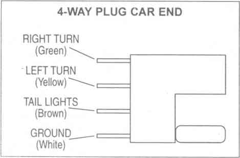
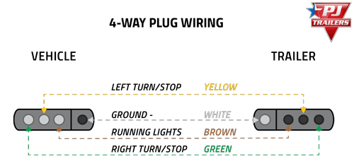
While the basic configuration is a 4 way flat connector that features one female and three male ends you may come across connectors with up to seven pins for additional functions that require wiring including electrically actuated brakes power source for a winch etc. By law trailer lighting must be connected into the tow vehicles wiring system to provide trailer running lights turn signals and brake lights. The trailer wiring diagram shows this wire going to all the lights and brakes. If your vehicle is not equipped with a working trailer wiring harness there are a number of different solutions to provide the perfect fit for your specific vehicle. Use a simple 4 way flat connector to power your 2 light trailer lights or use a custom vehicle specific trailer wiring harness. Plugs into the existing 4 way.
Also it must connect with things if included that use the aux power and back up lights too. Complete with a color coded trailer wiring diagram for each plug type this guide walks through various trailer wiring installation solution including custom wiring splice in wiring and replacement wiring. Basically it is another 12v circuit typically used for a reverse light reverse lockout for trailer brakes. Most of us arent electricians but that doesnt mean wiring a trailer or replacing corroded wiring is beyond us.
