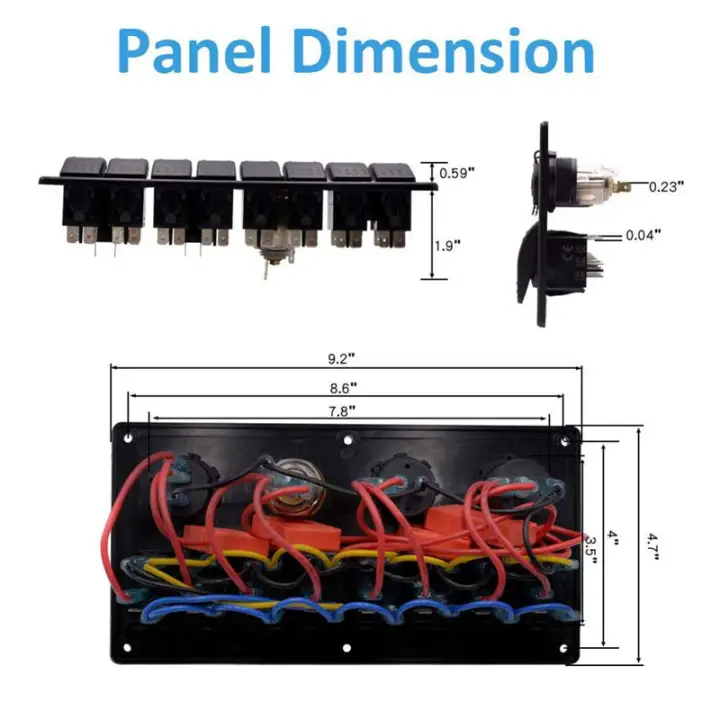
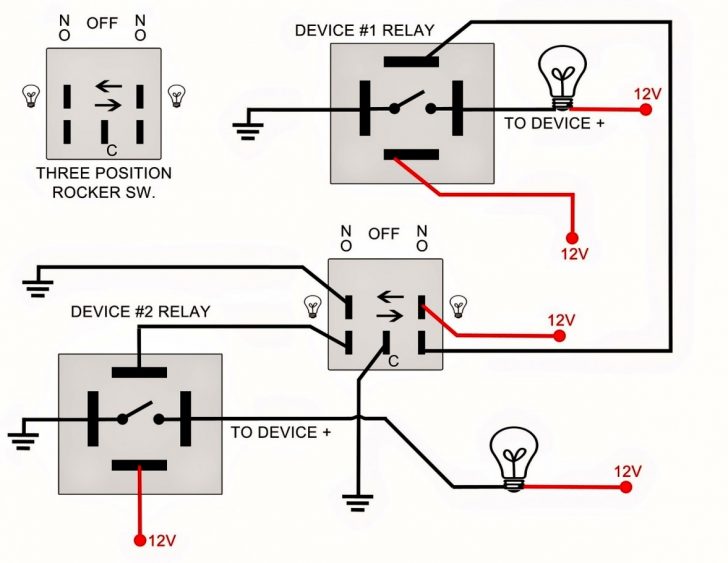
Each of our carling rocker switch bodies have the generic wiring diagram loaded into that products own page see photo right. We have wiring diagrams and wiring guides on how to wire a 10 terminal navancher on off on 3 way carling contura rocker switch as well as a wiring diagrams in how to wire a 10 terminal bilge auto manual on off on 3 way carling contura rocker switch for more on how to wire a bilge pump check this out we also have a general dpdt wiring diagram for powering two loads using an on off on 3 way carling.
How To Wire 6 Pin Dpdt Lighted Rocker Switch
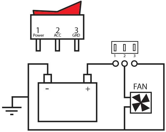
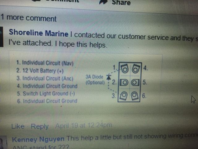
Shoreline marine illuminated rocker switch wiring diagram. Many of these switches though are quite flexible thought. Pin 2 is where the accessory that the switch is going to turn on is connected. Pin 3 is where the switch is either connected to ground or left open. I followed silvertips diagram when i wired my nav lights and they work fine except one of the lights on the switch doesnt work. Pin 1 is where the rocker switch receives the input power. It is the shoreline marine illuminated rocker switch.
Plus being etched there is no ink to ever wear off. I have a lighted rocker switch for my navanchor lights the switch has 6terminalss on the back and rocker has 2 lights 1 red 1 amber id like to include a picture of the switch but i dont know how the terminal layout is 2 on left 2 rt 2 middle when red end of rocker is depressed the 2 middle terminals and the 2 on the rt have continuity. Shoreline marine bilge pump 3 way switch wiring diagram the pump has two wires hot brown and ground black. Being laser etched vice printed these marine rocker switches look truly spectacular when backlit at night. The diagram below represents the schematic diagram for a spst rocker switch. Contura v switches can be placed onto white red or blue lighted switch bodies to match the look and feel of your boat.
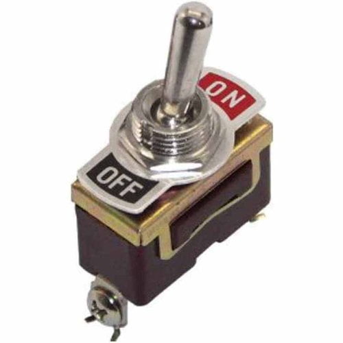
Occasionally the wires will cross. You might want to review the article on toggle switch wiring before proceeding. This is the most basic type of switch the onoff rocker switch as shown using ozniums black anti vandal toggle switch mounts in 16mm or 19mm hole. However it does not imply link between the wires. The section below has wiring diagrams the are specific to marine rocker switch panels. It has just 2 prongs.
An illuminated rocker switch is like a spst toggle switch with an extra terminal which allows the light to work. Not sure if i wired it wrong or if its a bulb issue. I have limited space and only room for 1 more switch which is why id like to wire it this way. According to earlier the lines at a illuminated rocker switch wiring diagram signifies wires. Rocker switch wiring diagram. With just a few small jumpers our switch selection can be used for a multitude of different functions.
Injunction of two wires is usually indicated by black dot on the junction of 2 lines. Also relays can be used to switch higher draw accessories to reduce switch load and voltage drop. The diagrams show conection of brown pump wire to float switch and an intemediary.
