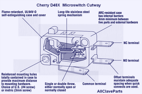
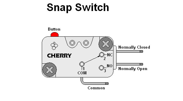
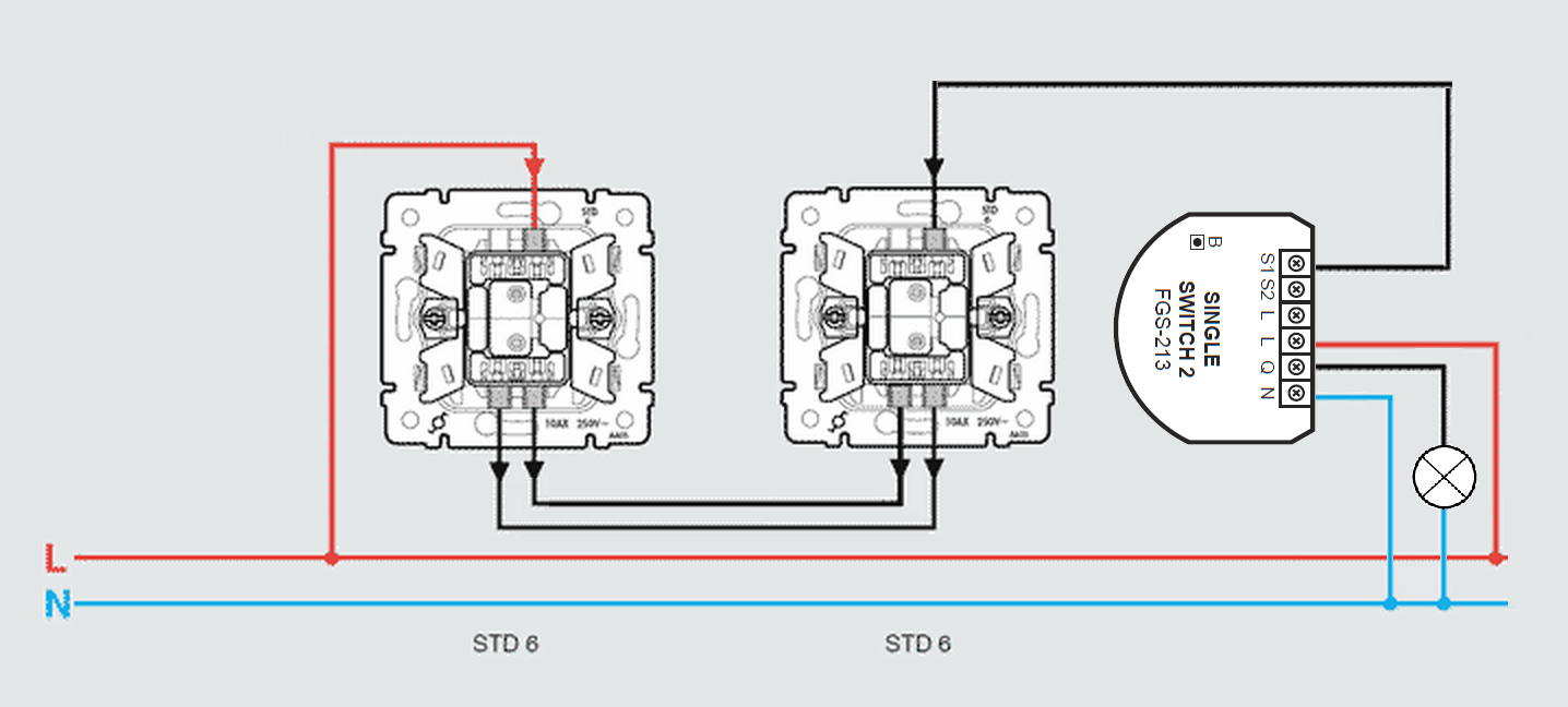
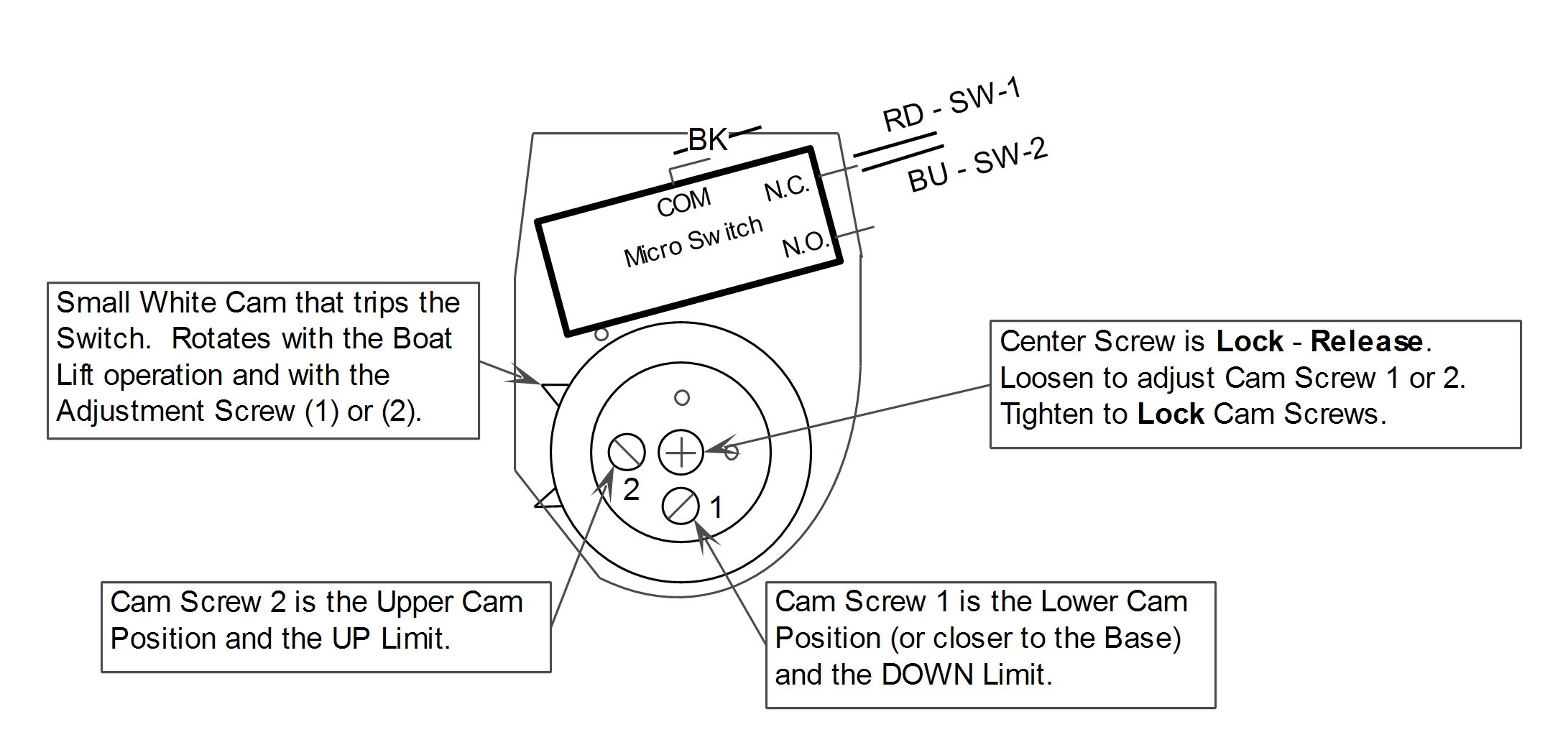
If not the structure will not work as it should be. Switch damage wiring must be rated to meet or exceed circuitry micro switch v basic standard v15 issue 3 circuit information a circuit diagram is included on the switch case labeling each of the terminals.

Single Micro Switch Controlling 3 Phase Motor Download
Micro switch diagram. The normal position corresponds to the switch. Inside a microswitch. Microwave runs with door open how to test microwave micro switch light wont go off when closed duration. You can fix it. The number of poles on a switch defines how many separate circuits the switch can control. Find great deals on ebay for club car micro switch.
Each part should be set and linked to other parts in specific manner. We hope this article can help in finding the information you need. Here is a picture gallery about micro usb wire diagram complete with the description of the image please find the image you need. A four pole switch can separately control four different circuits. For example if a. When the gas pedal micro switch goes bad it will not let the golf cart turn the motor over.
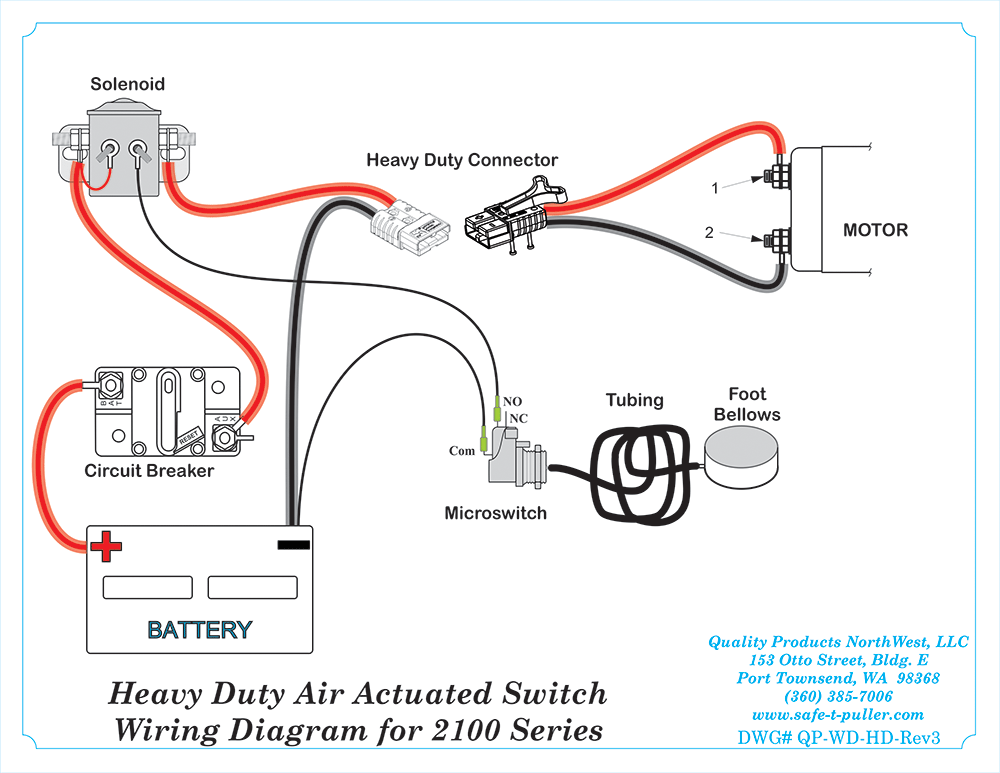
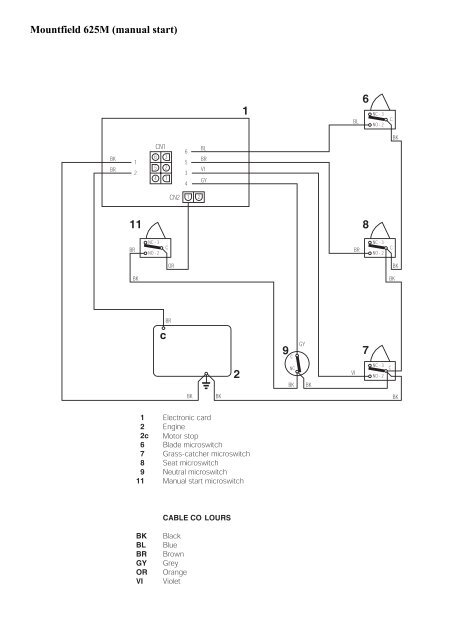
Ansul system wiring diagram ansul fire suppression system wiring diagram ansul system micro switch wiring diagram ansul system wiring diagram every electrical structure consists of various different components. Wiring diagram micro usb connector connections alexiustoday throughout micro usb wire diagram image size 631 x 480 px and to view image details please click the image. If you push the gas pedal down but your gas club car golf cart does nothing the micro switch is usually the first place to check. A switchs throw count defines how many positions each of the switchs poles can be connected to. So a switch with one pole can only influence one single circuit.

