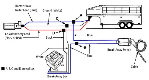
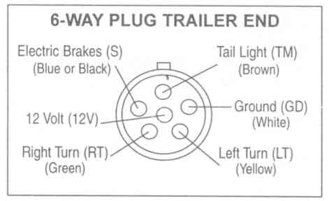
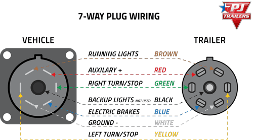
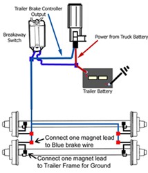
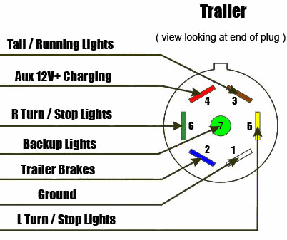
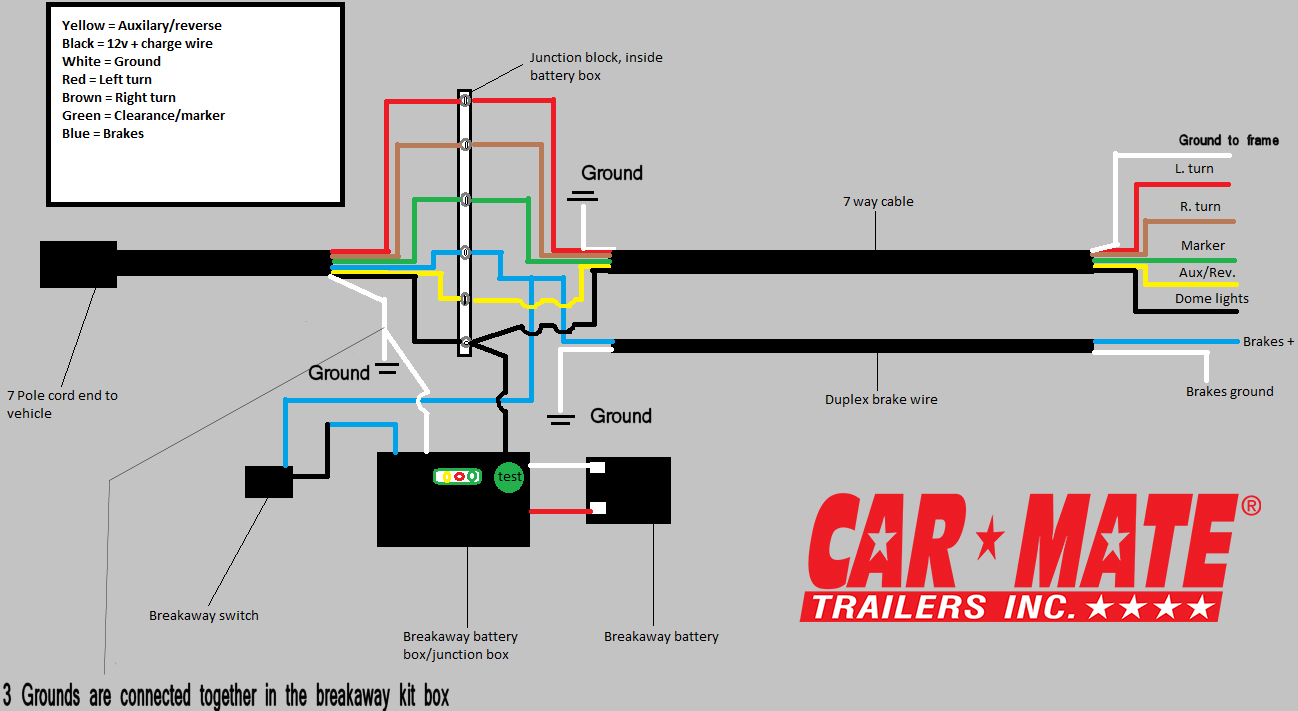
Trailer wiring diagrams trailer wiring connectors. Various connectors are available from four to seven pins that allow for the transfer of power for the lighting as well as auxiliary functions such as an electric trailer brake controller backup lights or a 12v power supply for a winch or interior trailer lights.
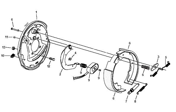
Utility Trailer Brake Wiring Diagrams H1 Wiring Diagram
Utility trailer brake wiring diagram. The four wires control the turn signals brake lights and taillights or running lights. 4 way trailer connectors are typically used on small trailers such as boat snowmobile utility and other trailers that that do not use brakes. Trailer wiring diagrams trailer wiring connectors various connectors are available from four to seven pins that allow for the transfer of power for the lighting as well as auxiliary functions such as an electric trailer brake controller backup lights or a 12v power supply for a winch or interior trailer lights. Redarc electric brakes wiring diagram best trailer brake wiring. That said for specific situations there are industrial standards with different connectors and wire arrangements. Wiring diagram trailer electric brakes inspirationa wiring diagram.
We recommend these standards because they are pretty universal. They also provide a wire for a ground connection. Wiring diagram trailer electric brakes best electric trailer brakes. Use on a small motorcycle trailer snowmobile trailer or utility trailer. Wiring diagram for utility trailer with electric brakes gallery collections of wiring diagram trailer electric brakes valid wiring diagram trailer. The following trailer wiring diagrams and explanations are a cross between an electrical schematic and wiring on a trailer.
Can also be used as custom wiring on trailers with 3 lightwire systems. The red and blue wire can be used for brake control or auxiliary. 4 way trailer connectors are. As the name implies they use four wires to carry out the vital lighting functions. See tow vehicle taillight wiring below.

