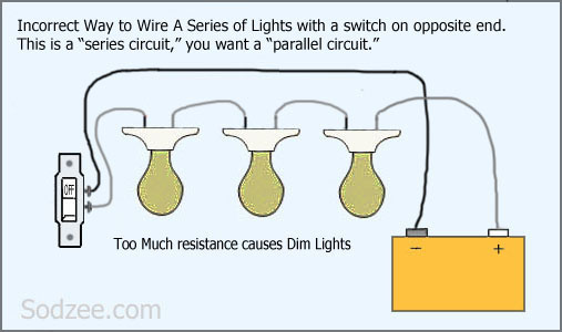
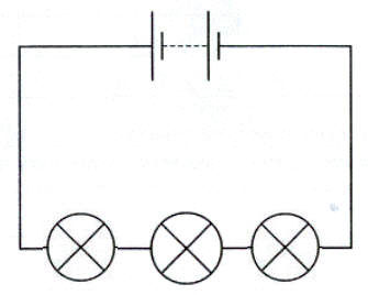
An electric circuit is an unbroken path along which an electric current exists andor is able to flow. Here you can see there is a cut in the line wire connected to lamp 3 so the bulb is switch off and the rest circuit is working.

Understanding Series Street Light Systems
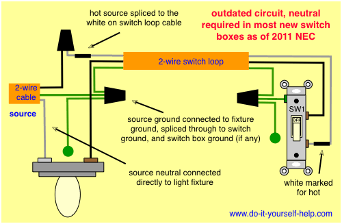
Series lighting circuit diagram. Series wiring can occur when errors are made or when manufacturers of decorative lighting sets use cheap designs. The regulator is. One was called an open loop circuit. Each lamp is connected between l and n. If you are not looking for information about wiring lights in series but rather wiring a series of lights together on one circuit the way the lights are connected is a parallel arrangement and not series. Also if we control each lamp by single way spstsingle pole single through switch in parallel lighting circuit we will be able to switch on off each bulb from from separate switch or if we switch off a bulb the rest lighting points wont affected as is it happens only in series lighting connection where all the connected load would be disconnected.
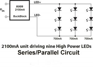
The forward voltage of each led at 700ma is 298v dc. Lets say we want to run a total of 9 cree xp l leds at 700ma each with a voltage of 12v dc. In this circuit a single conductor ran the entire loop of lamps and returned to the regulator. Another major defect of series lighting circuit is that as all lamps or bulbs are connected between line l and neutral n accordingly if one of the light bulb gets faulty the rest of the circuit will not work as the circuit will be open as shown in fig below. How electrical circuits work. The constant current regulator isolation transformer and.
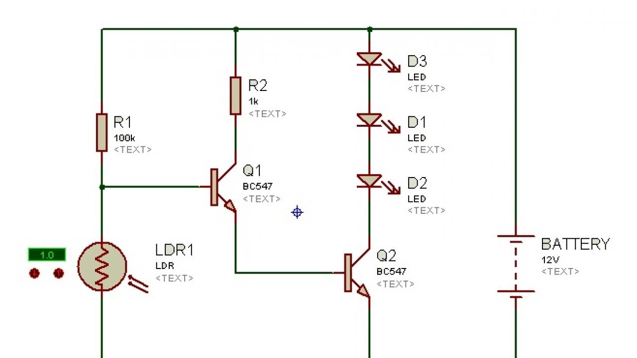
Figure 1 illustrates a basic open loop circuit. Faults in parallel lighting circuits. The following image shows the circuit diagram of the leds in series. This is in contrast to the more common use of constant voltage variable current circuits to supply electrical energy in everyday applications. Lets start with the series part of the circuit. Here three lamps are connected to the supply.
Rule number 2 from the series circuit bullet points proves that 12v dc. A series circuit is a closed circuit where the current follows one path. A series lighting circuit uses a constant current variable voltage source to supply electrical energy to the loads connected to the circuit. Thus all devices along the circuit stop working at the same time. There are two parallel rails l and n. In a series circuit the devices along the circuit loop are connected in a continuous row so that if one device fails or is disconnected the entire circuit is interrupted.
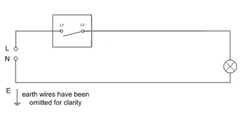
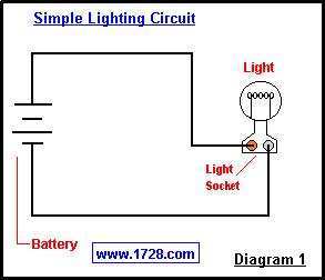
This is exactly the same wiring arrangement as the diagram on the overview page. A simple electrical circuit consists of a power source two conducting wires one end of each being attached to each terminal of the cell and a small lamp to which the free ends. The open loop design was the most economical as it required the least amount of conductor cable. In this circuit we will connect three 5mm white leds is series with the same 12v supply. Four types of series circuits were in common use. Circuit 2 of simple led circuits leds in series the next circuit in the simple led circuits project is connecting leds in series.
Wiring lights in series results in the supply or source voltage being divided up among all the connected lights with the total voltage across the entire circuit being equal to the supply. Circuit diagram of leds in series. As the name implies a seriesparallel circuit combines elements of each circuit.
