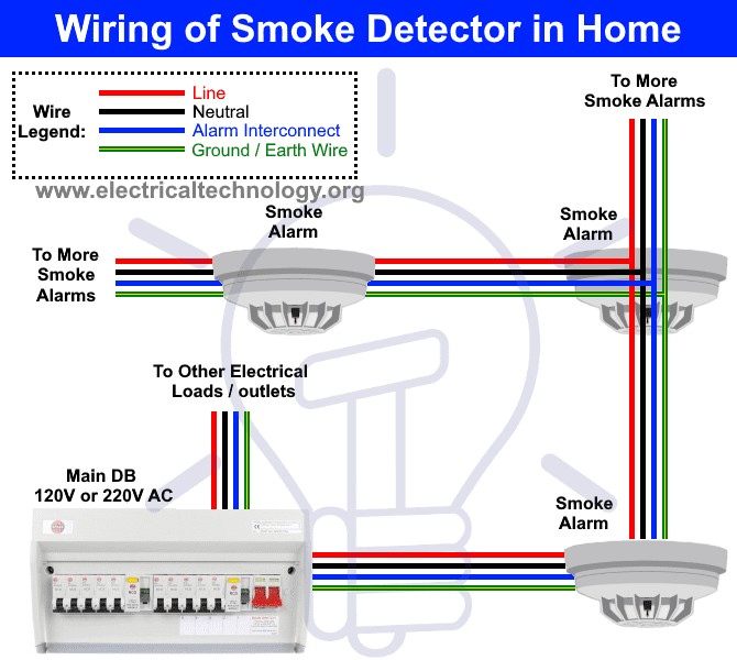
The low voltage smoke detector wiring is completely separate from the standard 110 volt smoke alarms and is wired in a specific way. Fire alarm systems are wired in industrial factories offices public buildings and nowadays even in homes.
Example Dsc Security System Burglar Alarm System
Residential fire alarm wiring diagram. Put fire alarms at both ends of a bedroom hallway or large room if the hallway or room is more than 30 feet long. Variety of fire alarm installation wiring diagram. Different types of fire alarm system such as conventional addressable intelligent and smart wireless designs are used for the same purpose ie. 1 people may know about a fire without hearing a smoke alarm. Interconnected smoke alarms increase safety. A wiring diagram is a simplified conventional pictorial depiction of an electrical circuit.
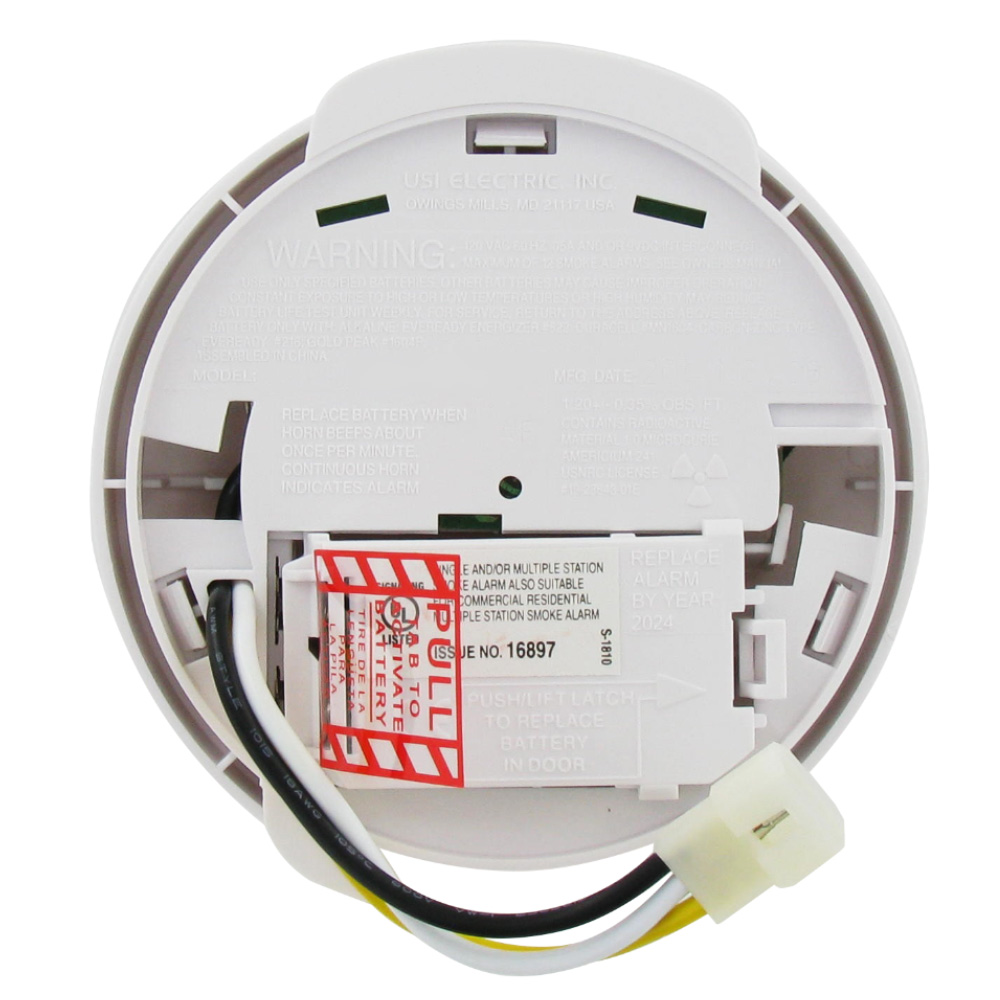
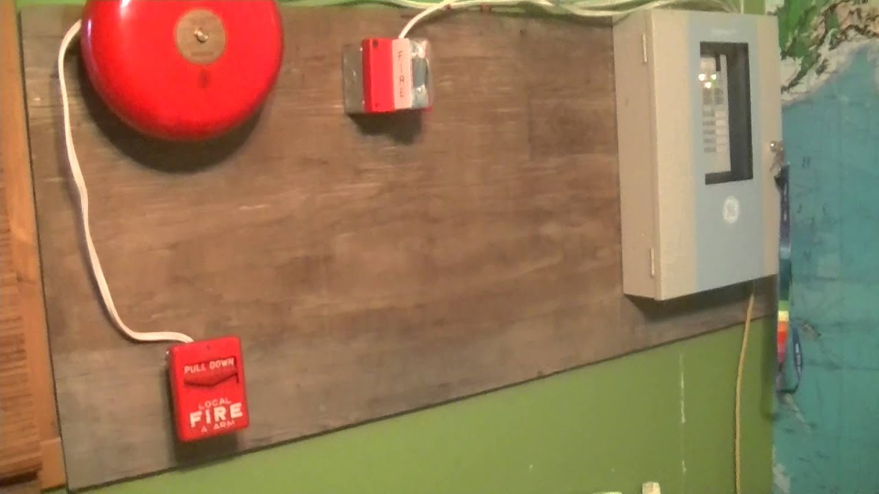
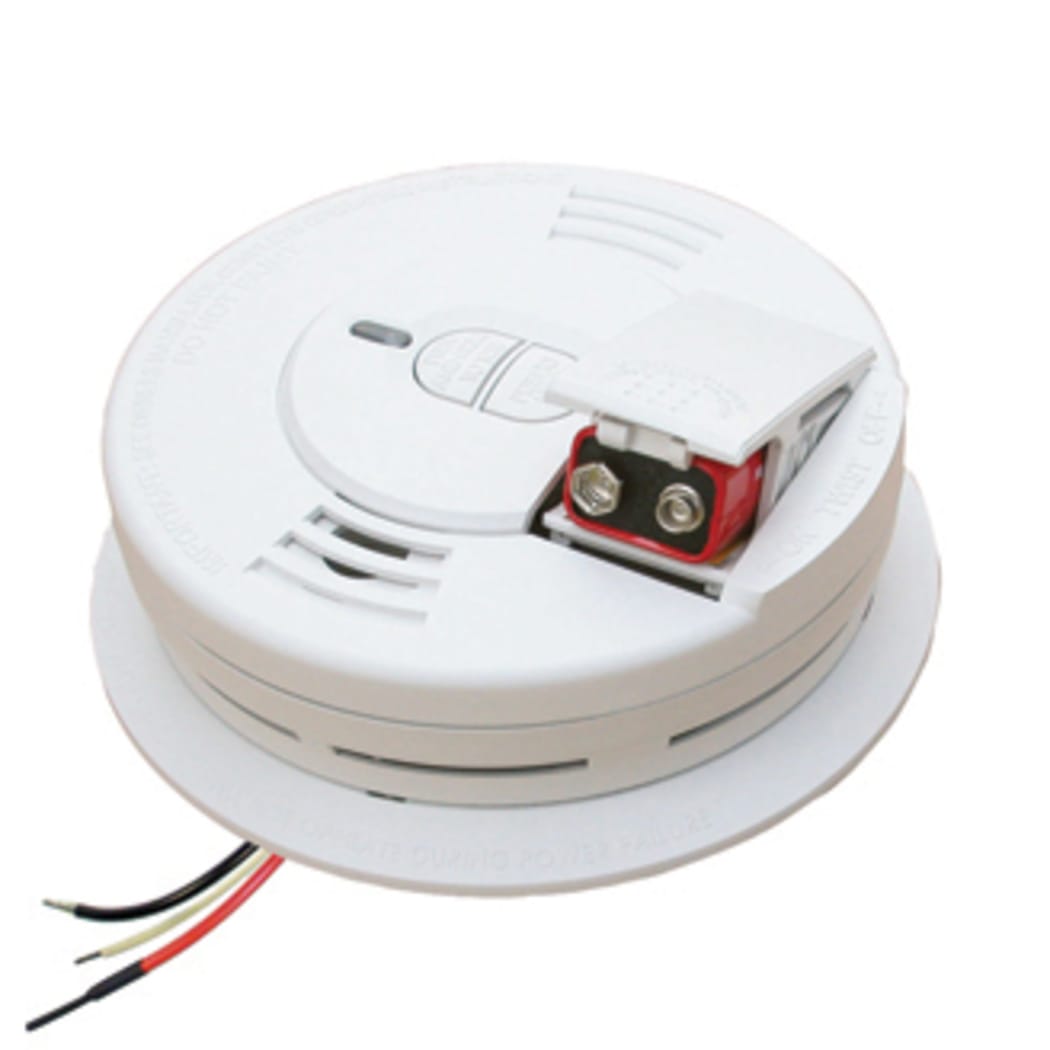
A wiring diagram is a streamlined conventional pictorial representation of an electric circuit. When mounting a fire alarm on the wall use an inside wall with the top edge of the alarm at a minimum of 4 10 cm and a maximum of 12 305 cm below the ceiling see diagram a. In case of emergency the sounders will operate to warn the people around to evocative via general or emergency exit. Fire wire is normally 22 gauge for residential use and can contain either 2 or 4 conductors. It shows the elements of the circuit as simplified shapes as well as the power as well as signal links between the devices. In a consumer product safety commission cpsc survey of households with any fires including fires in which the fire department was not called interconnected smoke alarms were more likely to operate and alert occupants to a fire.
When smoke alarms interconnected or not were on all. It shows the parts of the circuit as streamlined shapes as well as the power as well as signal connections in between the gadgets. Variety of fire alarm flow switch wiring diagram.
Gallery of Residential Fire Alarm Wiring Diagram


/SmokeDetector-e17afe58f9c147068db44d0eb85fa1d3.jpg)