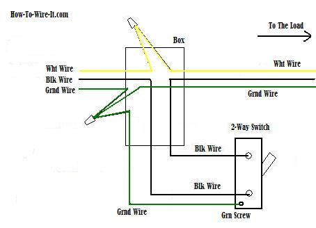
A dimmer switch is wired the same way as a single pole switch. Live neutral tails from the electricity meter to the cu.
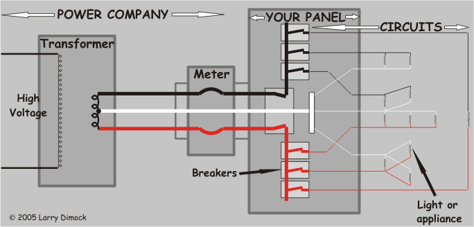
A Typical House Electrical Wiring In Wiring Diagram
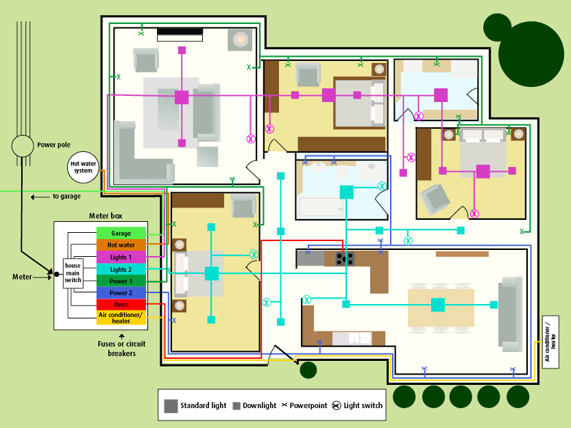
Typical house wiring diagram. Typical house wiring diagram illustrates each type of circuit. Lamp wiring diagrams wiring for a standard table lamp a 3 way socket and an antique lamp with four bulbs and two switches. For simple electrical installations we commonly use this house wiring diagram. In a typical new town house wiring system we have. Residences have historically used three kinds of home wiringphone lines homepna devices power lines and coaxial cabling for televisions and tv set top boxes. A typical set of house plans shows the electrical symbols that have been located on the floor plan but do not provide any wiring details.
A home building contractor will desire to validate the physical place of electric outlets as well as light fixtures making use of a wiring diagram to avoid costly errors and constructing code violations. 2 such rings is typical for a 2 up 2 down larger houses have more. This page takes you on a tour of the circuit. Doorbell wiring diagrams wiring for hardwired and battery powered doorbells including adding an ac adapter to power an old house door bell. The circuit map below is of a typical two bedroom house. The image below is a house wiring diagram of a typical us.
A split load cu. Ring circuits from 32a mcbs in the cu supplying mains sockets. In this illustration you can see the red hot lead wires of the dimmer are connected to the inbound black wire from the electrical source the electrical panel and the black wire that goes to the light fixtures black wire which in this case is a white wire that has been taped with black electrical tape. On example shown you can find out the type of a cable used to supply a feed to every particular circuit in a home the type and rating of circuit breakers devices supposed to protect your installation from overload or short current. Note that the dashed lines. In house wiring a circuit usually indicates a group of lights or receptacles connected along such a path.
Or canadian circuit showing examples of connections in electrical boxes and at the devices mounted in them. It is up to the electrician to examine the total electrical requirements of the home especially where specific devices are to be located in each area and then decide how to plan the circuits. Each circuit can be traced from its beginning in the service panel or subpanel through various receptacles fixtures andor appliances and back. Do it yourself lovers utilize wiring diagrams but they are likewise typical in house structure and also auto repair. The ability to plug devices together across these different cable types and create a whole house wired home network is being developed by a group called the homegrid forum.
