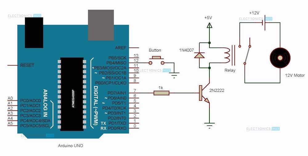
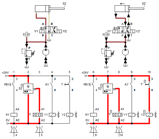
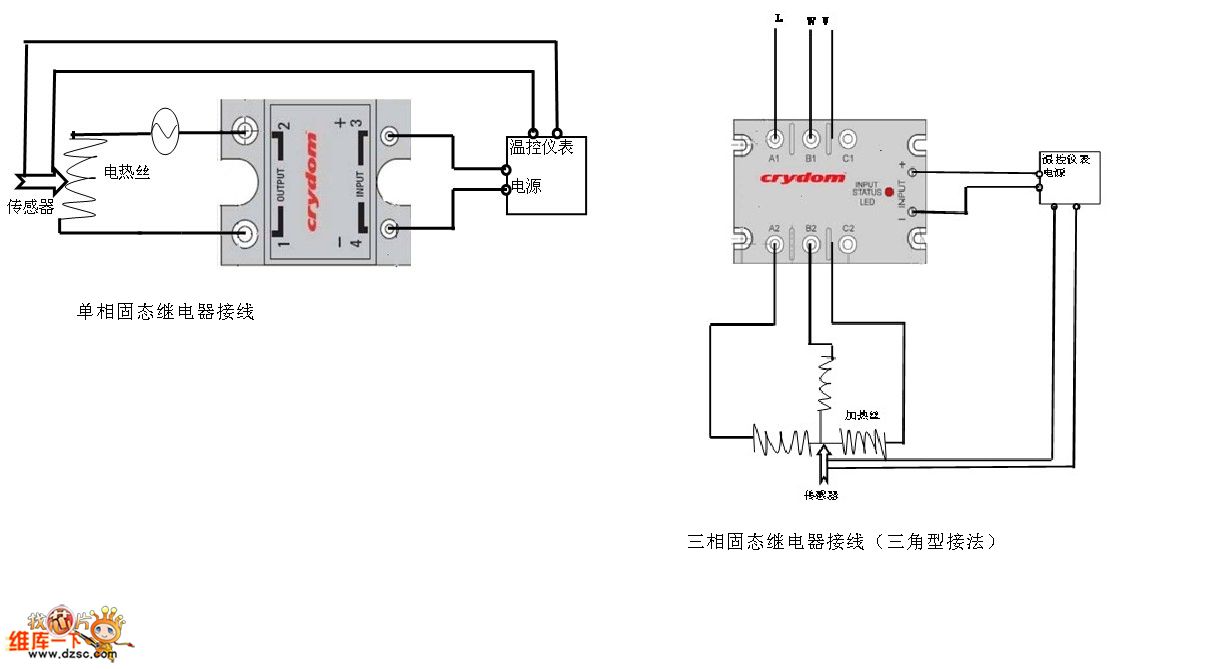
Its using relays to control the circuit and also the diagram will begin to take the shape of a ladder as the relay logic grows. We have connected transistor base to arduino pin a0 through a 1k resistor.

How To Wire Contactor And Overload Relay Contactor Wiring
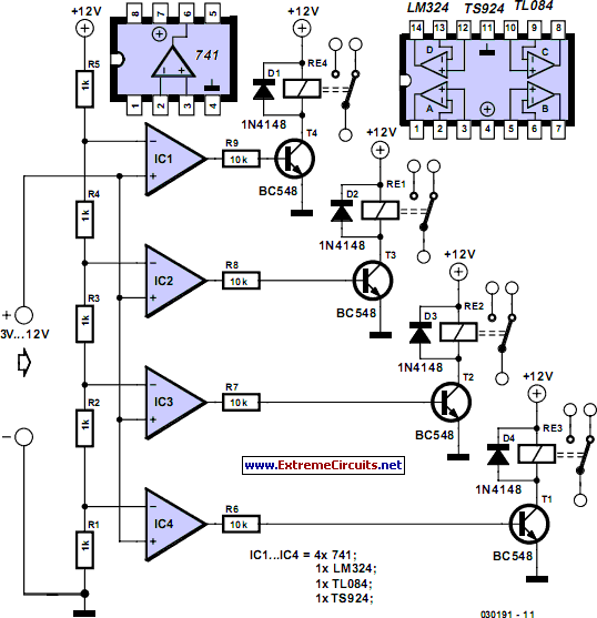
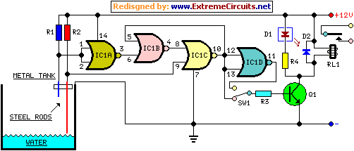
Relay control circuit diagram. In this arduino relay control circuit we have used arduino to control the relay via a bc547 transistor. Now these diagrams are known as relay logic or ladder diagrams. Relay logic diagrams represent the physical interconnection of devices. A wiring diagram is. 555 integrator with transformer relay with relay schematic circuit diagram. An ac bulb is used for demonstration.
The control circuit is the part of the relay that determines when the output component is energized or de energized. Audio spectrum analyzer dspic30f6012 mcp6022. It will continue downward as you will see later on. Schematics are generally easier to read and understand than wiring diagrams. Circuit diagram and working. Schematic diagrams are used to troubleshoot and install control circuits.
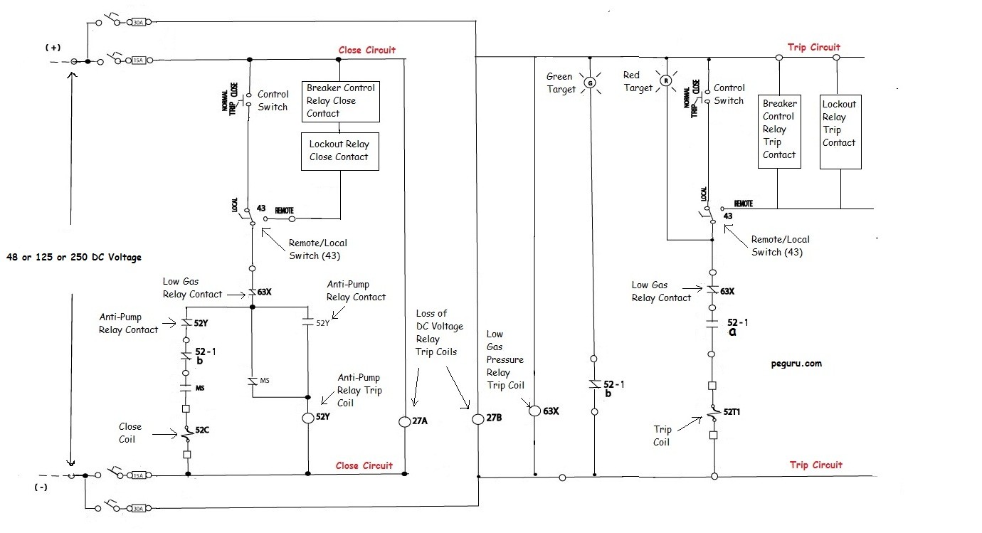
A notation we might sketch using pencil on a diagram to help us follow the operation of the circuit. Jun 30 2020 explore juni joness board circuit diagram on pinterest. Hand held simple magnetized demagnetized device schematic circuit diagram. Schematic diagrams schematic diagrams show components in their electrical sequence without regard for physical location. An actual ladder diagram of a relay based motor control system is shown here complete with red line edits showing modifications to the circuit made by an industrial electrician. The relay logic circuit forms an electrical schematic diagram for the control of input and output devices.
Each rung would have a unique identifying reference number and the individual wires on that rung would have wire numbers as a derivative of the rung number. Wiring diagrams wiring diagrams show components mounted in their general location with connecting wires. Perhaps the most confusing aspect of relay control circuits for students to grasp is the meaning of normal as it applies to the status of relay contacts. Pic16f877 4 layer elevator control circuit schematic circuit diagram. In electromechanical relays the coil accomplishes this function. Below given is relay driver circuit to build your own relay module.
When analyzing the operation of a relay control system it is helpful to have some way to temporarily denote the conductive status of switch contacts and the energization status of relay coils ie. In this particular case i show a low voltage control circuit and a 3 phase higher voltage motor. The control circuit functions as the coupling between the input and output circuits. Kty10 lm2903 temperature sensor relay control schematic circuit diagram. Now in the diagram below i have added a motor starter. There you have it.
A very common form of latch circuit is the simple start stop relay circuit used for motor controls whereby a pair of momentary contact pushbutton switches control the operation of an electric motor. See more ideas about circuit diagram circuit electronics circuit.
