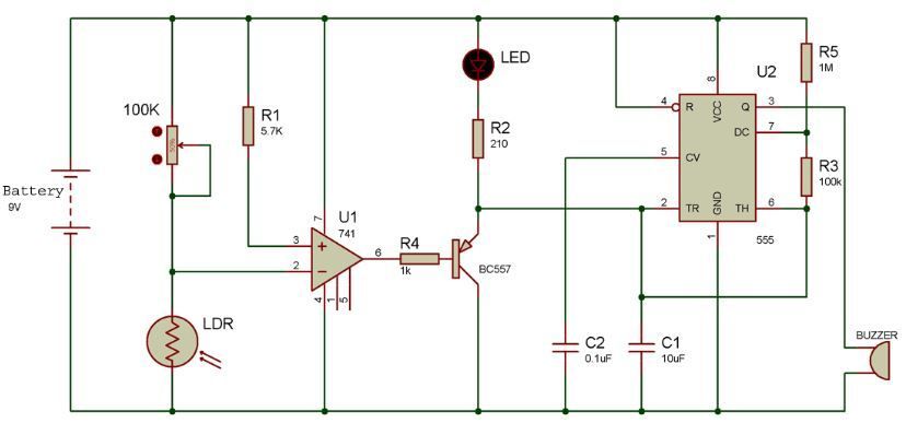
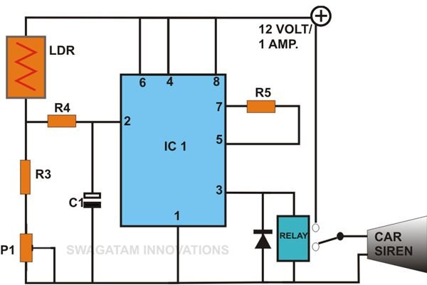
Basically fence lighting is used for security purpose and can be used at various place. Ldr is placed facing towards the entrance and a potentiometer is used to adjust the sensitivity of the device.
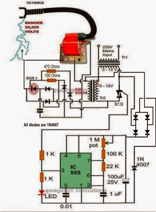
A Homemade Fence Charger Energizer Circuit Homemade
Automatic fence lighting with alarm circuit diagram. You can also add a switch between the negative pin of the battery and ldrs grounded pin to control this security system manually. Tutorial video on how to make automatic lighting fence circuit with alarm using op amp 741 and timer ic 555. Ldr is placed facing towards the entrance and a potentiometer is used to adjust the sensitivity of the device. The complete circuit diagram for automatic fence lighting with alarm is shown above. You can also add a switch between the negative pin of the battery and ldrs grounded pin to control this security system manually. General purpose hobby circuit of a simple light fence security beeper is presented here.
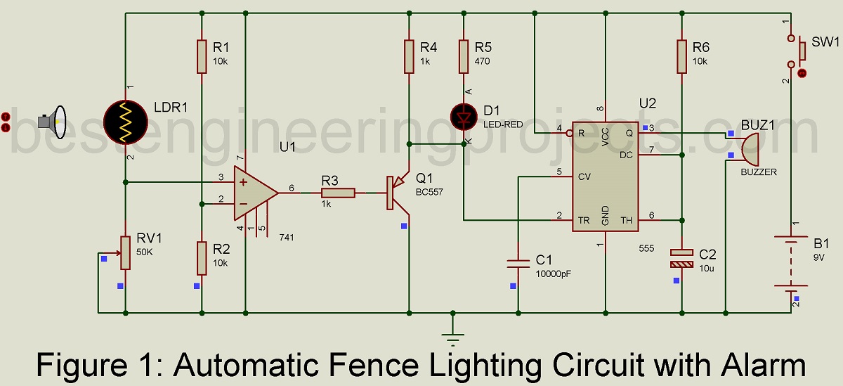
The complete circuit diagram for automatic fence lighting with alarm is shown above. You can also add a switch between the negative pin of the battery and ldrs grounded pin to control this security system manually. Any 12 volt dc power supply can power the whole circuit. Working of this circuit is straight forward. The circuit of automatic fence lighting circuit with alarm is shown in figure 1. Ldr is placed facing towards the entrance and a potentiometer is used to adjust the sensitivity of the device.
Ldr is placed facing towards the entrance and a potentiometer is used to adjust the sensitivity of the device. The construction of this project is very simple and is built around readily available electronics components like op amp 741 timer ic 555 pnp transistor bc557 led piezo buzzer and few other passive components like resistor and capacitors. The project construction of automatic fence light controller has been done primarily as a photo type design it could be further modified suit the situation where it will be used eg when used to activate an alarm the led could be further modified to suit the situation where it will be used eg when used to activate an alarm the led could be. Automatic lighting fence circuit the circuit uses a voltage comparator and a monostable timer to give the warning alarm on detecting a moving person. Automatic light fence circuit diagram with alarm light fence circuit is used to detect the presence of any human or object in a particular area. The complete circuit diagram for automatic fence lighting with alarm is shown above.
Circuit diagram complete circuit diagram for automatic fence lighting with alarm is shown above. The detecting range of light fence circuit is about 15 to 3 meters. You can also add a switch between the negative pin of the battery and ldrs grounded pin to control this security system manually. This circuit can be used as a door alarm gate alarm pathway alarm etc. Ic µa741 ic1 is used as a voltage comparator with two potential dividers in its inverting and non inverting inputs.
