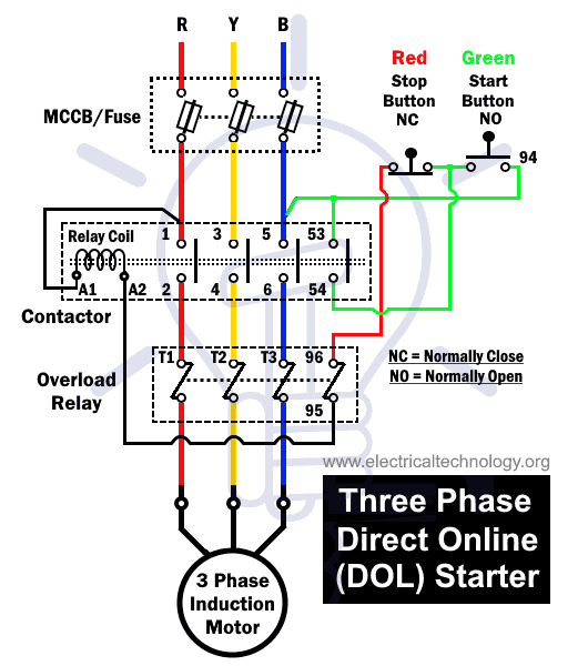
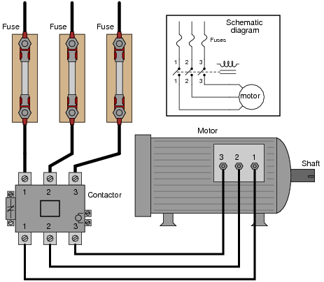
A wiring diagram is a kind of schematic which utilizes abstract photographic icons to show all the affiliations of components in a system. In short this the complete guide of forward reverse starter.
3 Phase Motor Starter Wiring Diagram H1 Wiring Diagram
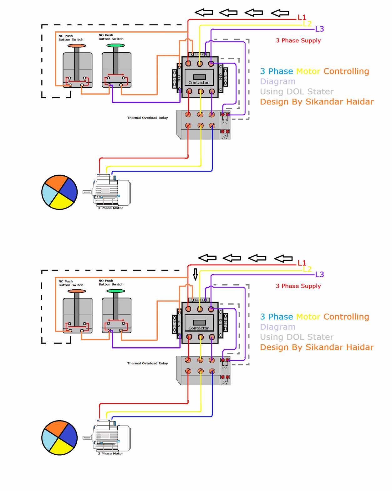
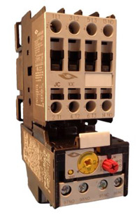
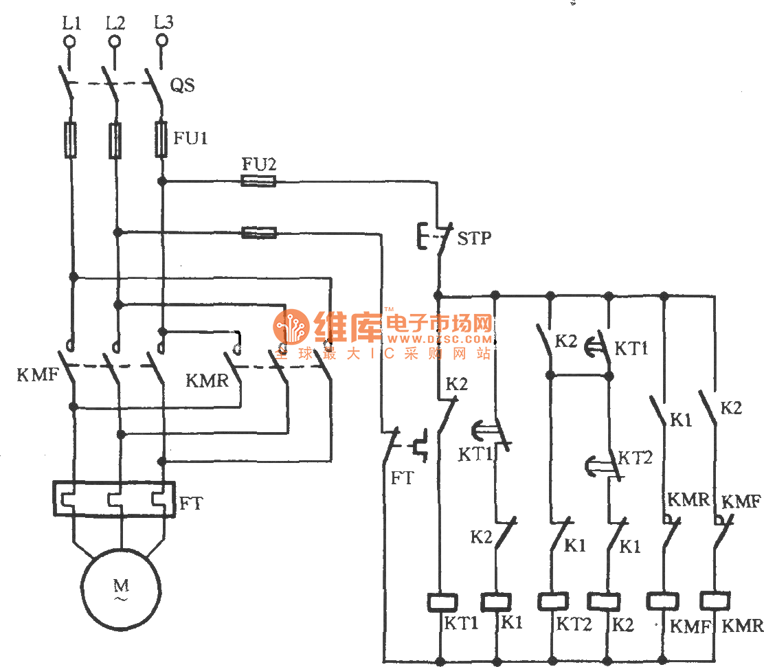
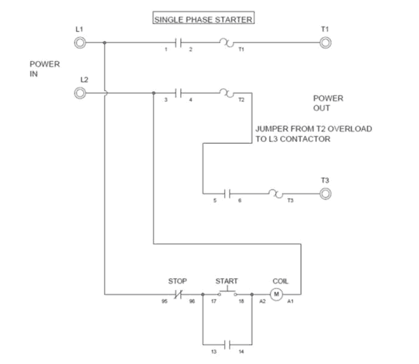
3 phase motor starter wiring. I shown the 3 pole mccb circuit breaker 2 magnetic contactor normally open normally close push button switch thermal overload relay 3 phase 4 wire system supply 3 phase motor with connection trip indicator light etc. Signs that stand for the components in the circuit as well as lines that represent. Star delta y δ 3 phase motor starting method by automatic star delta starter with timer. A motor starter is a combination of devices used to start run and stop an ac induction motor based on commands from an operator or a controller. A three phase motors large size and high starting torque usually limit its use to industrial settings. Three phase motor connection schematic power and control wiring installation diagrams.
A wiring diagram is a streamlined conventional photographic representation of an electrical circuit. 3 phase motor starter wiring diagram sample exactly whats wiring diagram. Three phase electric motors use three different electric legs with a 13 cycle lag between them. It shows the parts of the circuit as simplified shapes and also the power and also signal links in between the tools. To use three phase electricity a motor needs windings spaced 120 degrees apart. Three phase motor connection stardelta without timer power control diagrams.
Wiring diagrams are comprised of two things. The motors starter wires directly to the motors wire terminals. In north america an induction motor will typically operate at 230v or 460v 3 phase 60 hz and has a control voltage of 115 vac or 24 vdc. Time lapse of schematic diagram drawn into a wire diagram and the wiring of the magnetic motor starter. In the 3 phase motor forward reverse starter wiring diagram. Assortment of 3 phase motor starter wiring diagram pdf.

