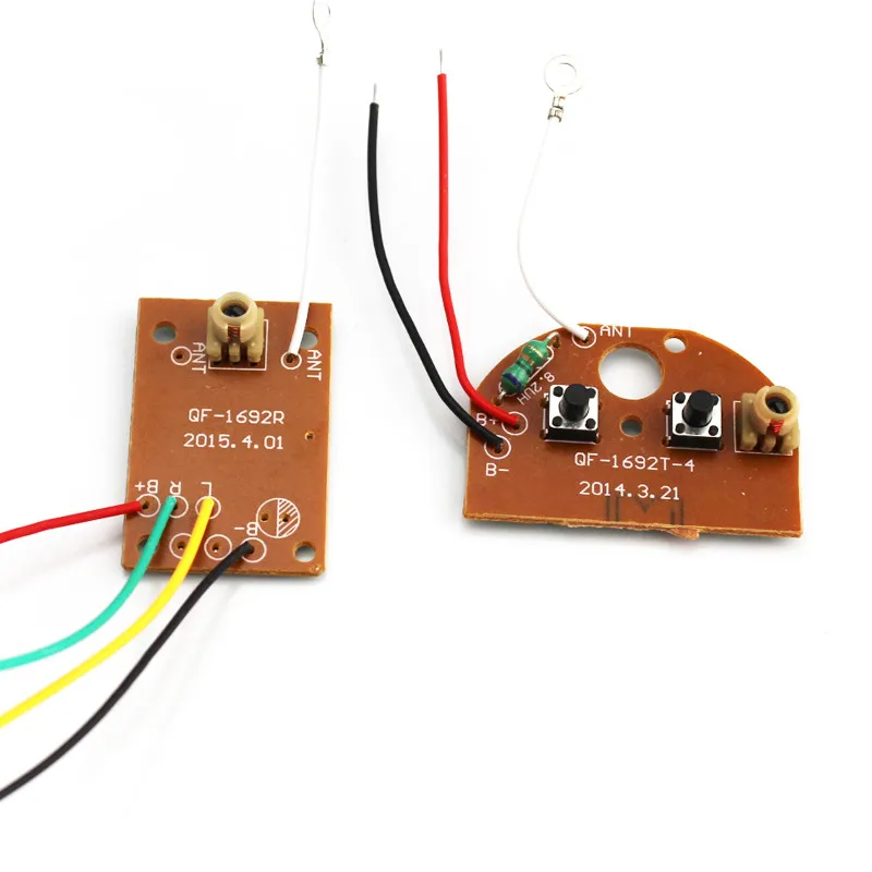
As with anything else in life it will take some practice to learn and perfect anything. The desired 433mhz rf remote module could be procured from any online store or from your nearest electronic dealer.
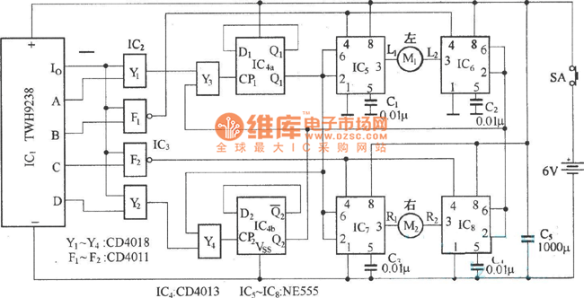
Electric Car Remote Control Circuit Diagram
Rc car remote control circuit diagram. The range of the remote control should be as per the required specifications of the rc helicopter range here its supposed to be within 1km. We will have two switches in our remote control to power each motor of the car. The state of the switches onoff is the control data. It uses simple integrated circuits ic and it is controlled wirelessly by a remote controller. Et discover 100838 views. This data from the remote control is encoded before transmission received back and.
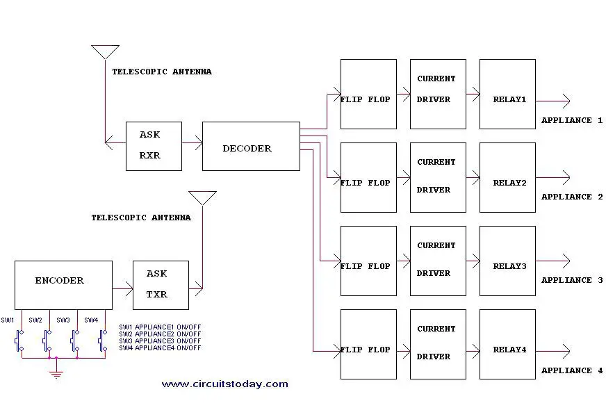
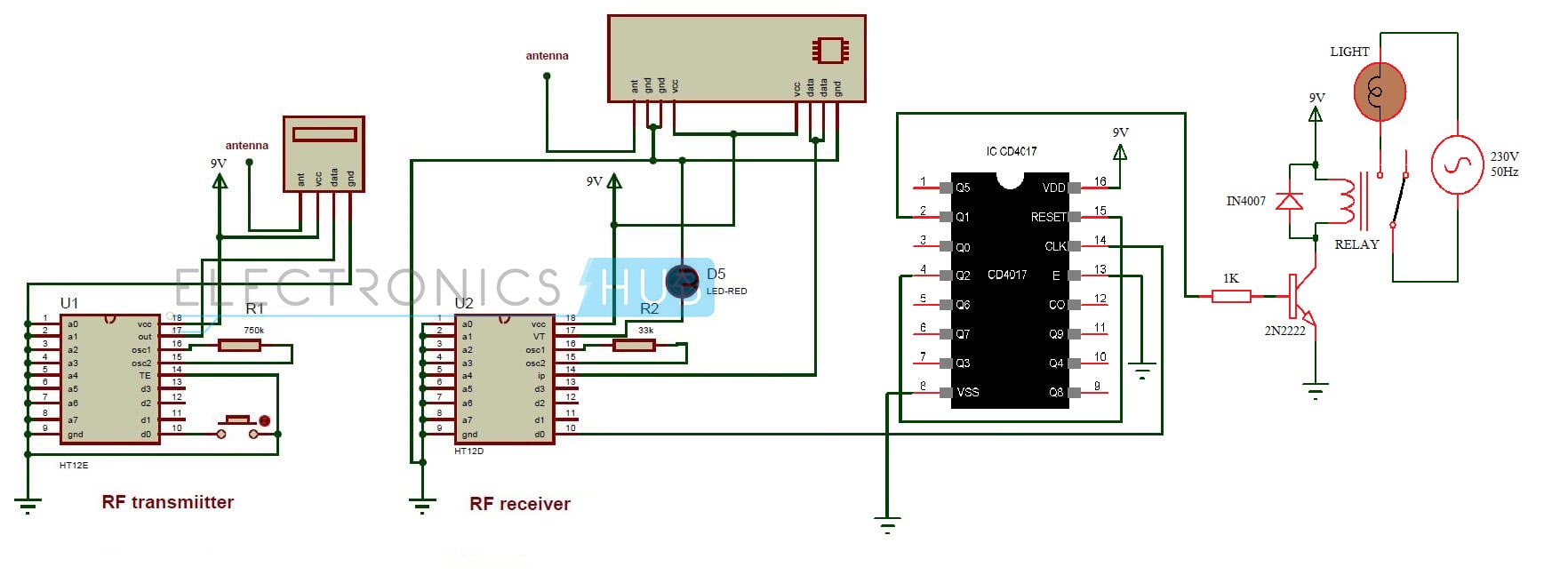
Receiver circuit is connected to ac appliance via relay so that we can control the light remotely. This circuit completes your rc car. To operate the toy car you need to hold the transmitter in your hand keeping it pointed at the toy car which has the receiver fitted inside and simply press a switch provided on. It has an rf receiver connected to a decoder to decode the data sent by the transmitter which is situated on the remote control. Suggested by umg justin bieber yummy official video song favorite girl album version. We have used ic 4017 to convert it into a push on push off switch.
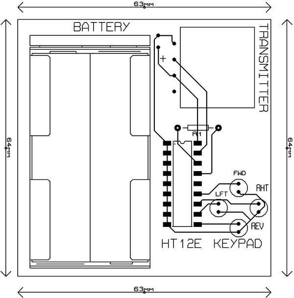
For the discussed rc helicopter remote control circuit a 6 channel rf remote module. The rc car decodes the signal and moves accordingly. The rc car is a great project for all ages and it doesnt require any programming. The keypad for our remote is made up of four individual buttons which is wired to the data pins of the data pins ad0 to ad3 of the encoder ic. Images of circuits of rc control car and remote. The decoded 4 bit data is given to the motor driver as input logic to drive the vehicle.
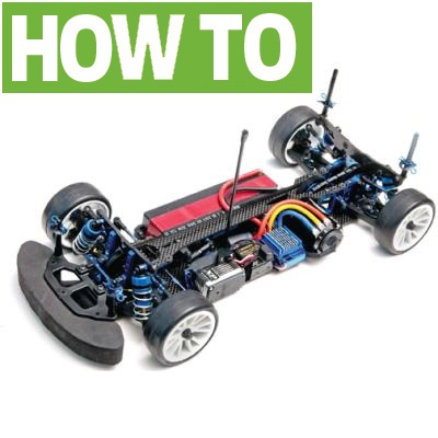
In this remote controlled switch circuit we are using tv remote to onoff the ac light by pressing any button of remote and using the tsop1738 at receiver end. The above remote control circuit consists of three important components keypad encoder ic ht12e and a rf transmitter rf433 module. The remote controller sends out a encoded radio frequency rf signal to the rc car. This remote controlled toy car circuit consisting of an infrared transmitter receiver pair uses ir beam transmission to switch the toy car on or off. Though a team associated tc61 sedan was used for this article the same concepts can be used when wiring up off road. How to make ir 4 channel remote control system.
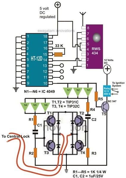
Given above is the circuit diagram for the receiver which is situated on the rc car. When the crew at rc car action reviews a car we follow the same steps while installing electronics to get a vehicle ready for photos. Free pcb files and circuit diagram. Circuit diagram of remote control. 4 channel rf transmitter receiver with motor controller for rc car. The brief idea is to transmit control signals through radio frequency and receive it through a receiver module in the car.
