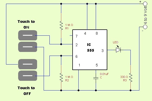
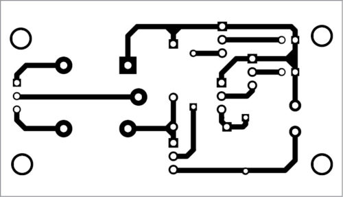
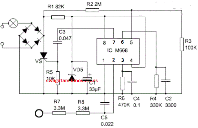
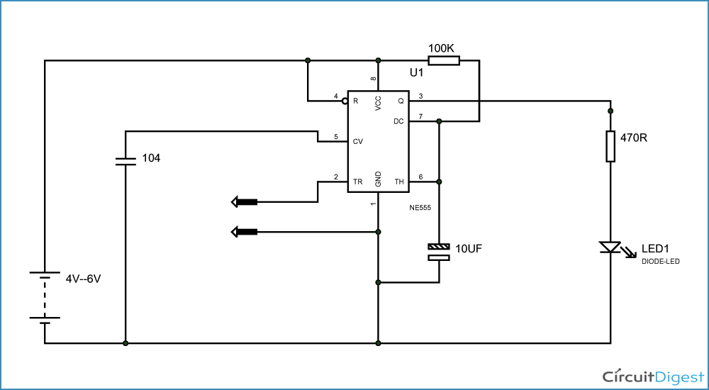
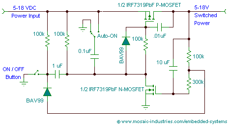
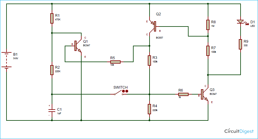
Touch switch circuit project. The contacts an be made with just two loops of wire close together or two squares etched close together on a pc board.
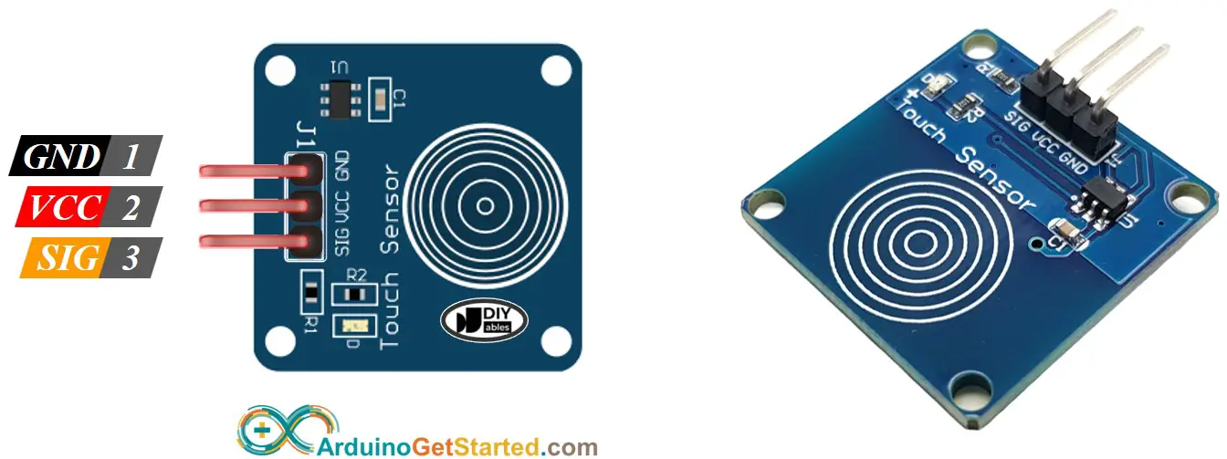
Arduino Touch Sensor Arduino Tutorial
One touch switch circuit diagram. Few electronic elements only available in the market with high sensitivity and high reliability. In this video i will show you how to make touch on touch off switch with relayon off switchlatching relay the correct schematic diagram of this circuit. As you know nese 555 is a very popular timer ic with multiple applications in different projects. A very simple touch switch circuit diagram can be constructed using this circuit schematic. When activated the output of the circuit goes high for about one second. 1 x 555 timer ic.
This diagram illustrates wiring for one switch to control 2 or more lights. The counter circuit is a cdb490 type and is capable to show at pin 12 states. 1 x 33 mω resistor 14 watt 1 x 1 mω resistor 14 watt 1 x bulb with holder regular or cfl 1 x 5v relay module if relay module is not available then you need the following components 1 x 5v. A touch switch is basically a simple switching circuit activated upon a touch. Working of the circuit is straightforward. The source is at sw1 and 2 wire cable runs from there to the fixtures.
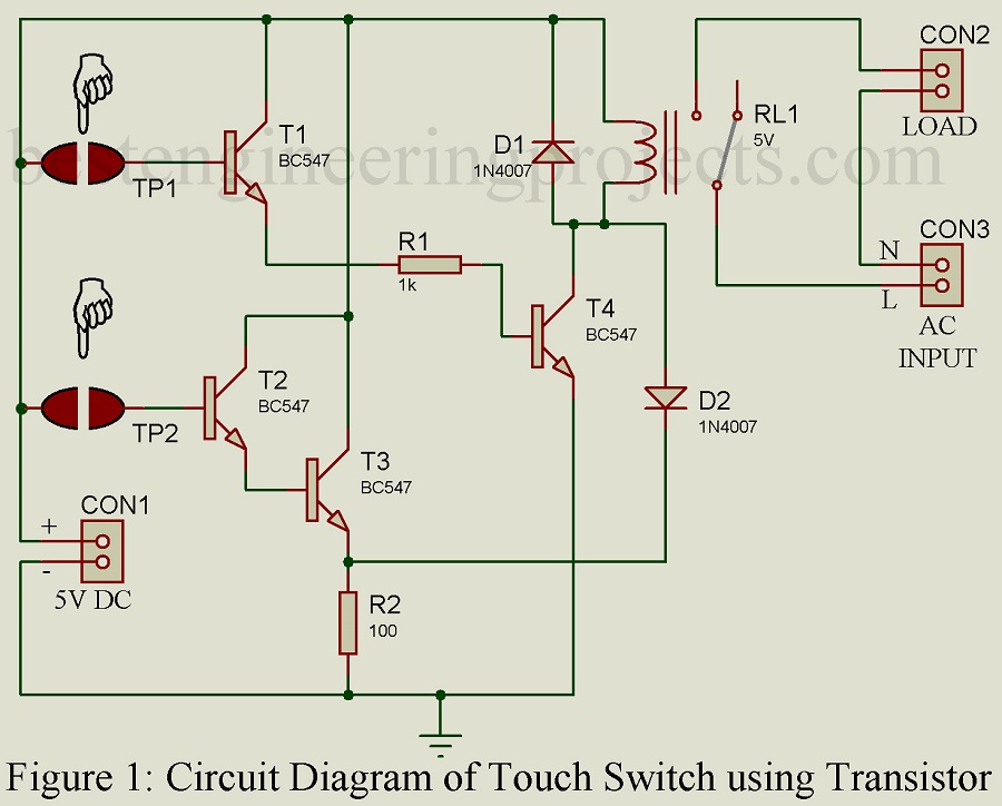
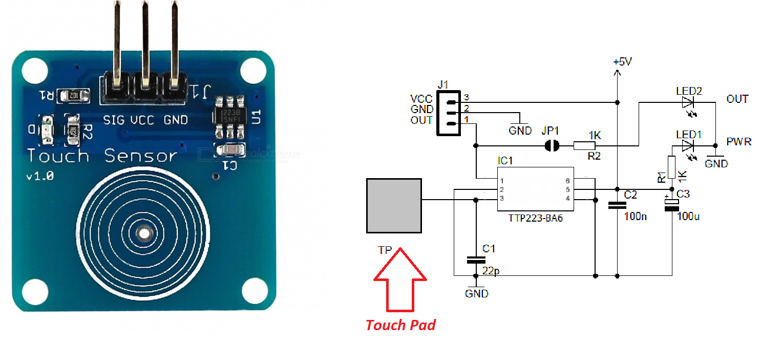
Here the ic at42qt1012 from atmel is in the top preferred list to us. Share on tumblr electronic circuits with touch sensing is more interactive to the user than traditional electronic circuits. The circuit works off 5v dc. This circuit will turn on off an electronic relay using the same touch sensor. It is built around four bc547 transistors t1 through t4 a 5v single changeover relay rl1 two 1n4007 diodes d1 and d2 and two touch plates tp1 and tp2. This pulse can be used to drive a relay transistor other logic etc.
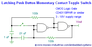
A simple touch switch circuit diagram is shown in figure 1. Touch switch circuit notes. The at42qt1012 is an one channel toggle mode touch sensor ic with power management functions. The hot and neutral terminals on each fixture are spliced with a pigtail to the circuit wires which then continue on to the next light. I use ic 4011 digital cmos is base of a circuit. The circuit diagram for the touch on and off switch circuit is shown in the below image.
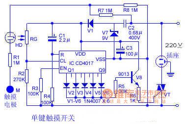
Today we let to play a simple digital circuit. It is set to form as flip flops. Multiple light wiring diagram. It is a one shot touch switch control. This touch switch circuit is composed from an current amplifier and a decimal counter circuit. If youre new to 555 ic please take the time to read our beginners guide on 555 ic.
You have the diagram on how to connect the wires is very simple just connect the load in this case the 12v bulb to the terminal of the 9v battery and the terminal of the load to the middle pin of the mosfetthe negative terminal of the battery to the right end side terminal of the mosfetand thats it you have an old school touch switch. Circuit diagram of the touch switch. In this project guide were building a touch switch circuit using ne 555 ic. The logic hi at an output when your finger touchpad and is a time delay for 3 seconds.
