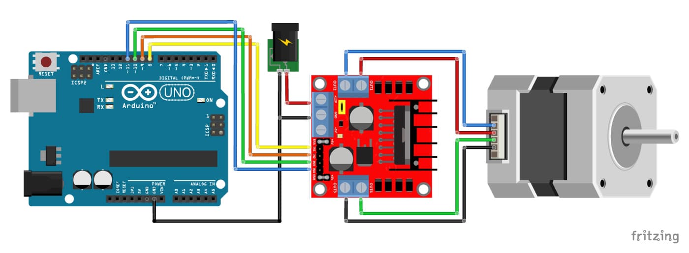
2018 24v36v48v 250w350w bldc motor speed controller 6 mosfet dual. 36v 800w set electric bike controller twist throttle brake lever.

Electrical And Electronics Engineering Types Of Motor
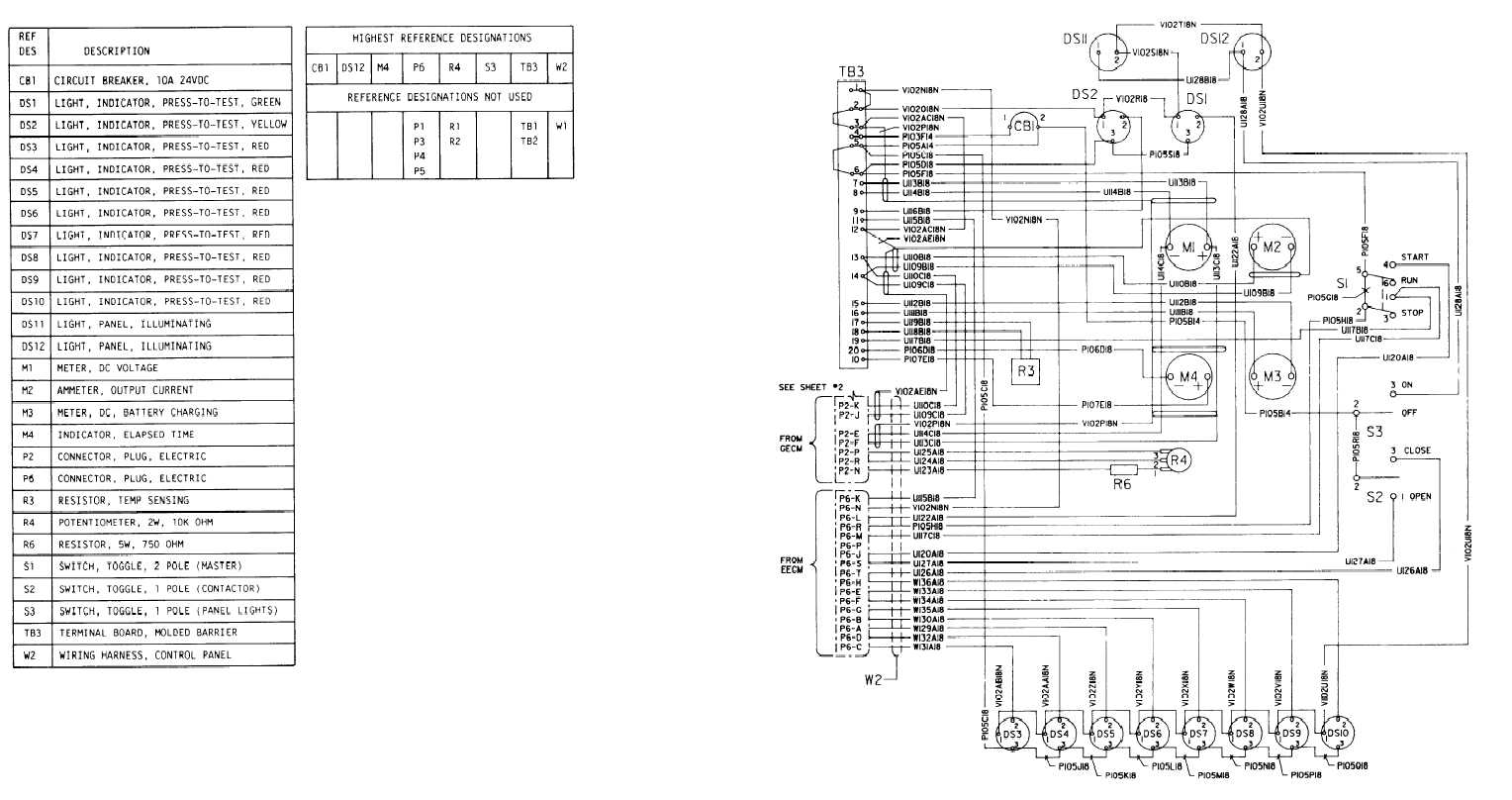
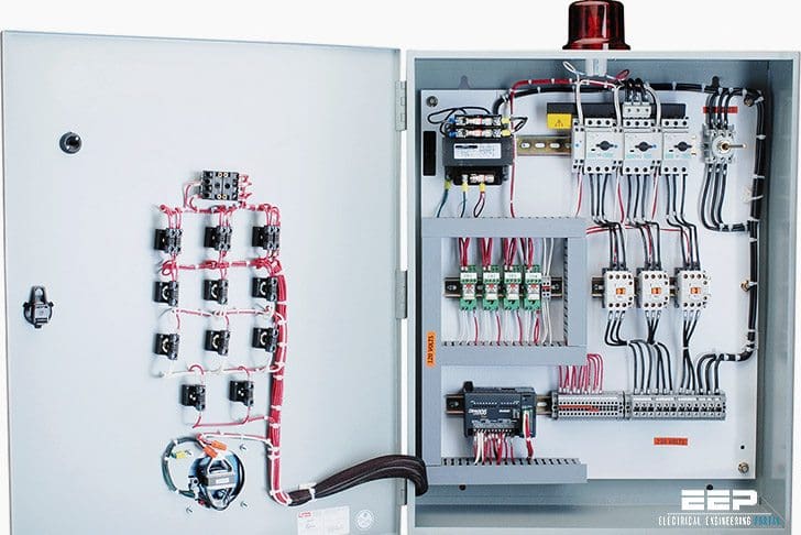
Motor control panel wiring diagram. Motor control wiring diagram pdf wiring diagram is a simplified usual pictorial representation of an electrical circuitit shows the components of the circuit as simplified shapes and the facility and signal associates with the devices. Figure 1 typical wiring diagram. Show the control circuits only power circuits are omitted for clarity since they can be traced readily on the wiring diagrams heavy lines. Forward reverse motor control diagram for three phase motor for three phase motor forward reverse control circuit. Three phase motor connection schematic power and control wiring installation diagrams. A wiring diagram is a simplified traditional photographic representation of an electrical circuit.
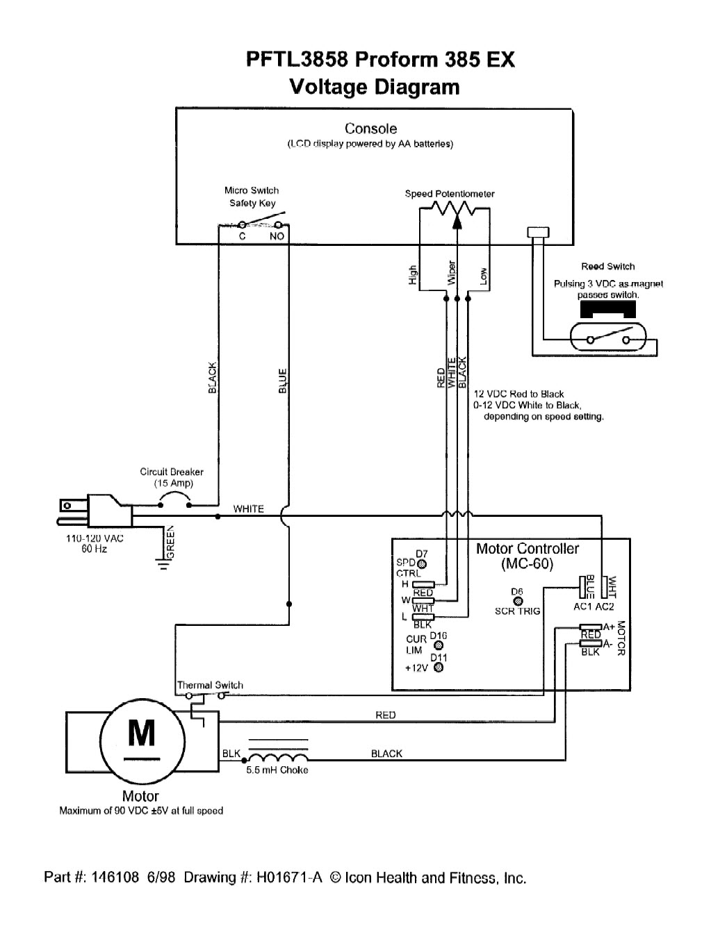
Dashed lines indicate a single purchased component. It reveals the parts of the circuit as streamlined shapes and the power and also signal links in between the gadgets. We use 2 magnetic contactors as forward reverse switch. E bike controller wiring diagram collections of e bike controller wiring diagram list diagram electric bike. They can be used as a guide when wiring the controller. Three phase motor connection stardelta without timer power control diagrams.
Here i showed the forward reverse wiring diagram. It is also common for a control cabinet to supply a higher voltage to other equipment such as motors. The above diagram is a complete method of single phase motor wiring with circuit breaker and contactor. Note that symbols are discussed in detail later. E bike controller wiring diagram recent wiring diagram electric bike. They show the relative location of the components.
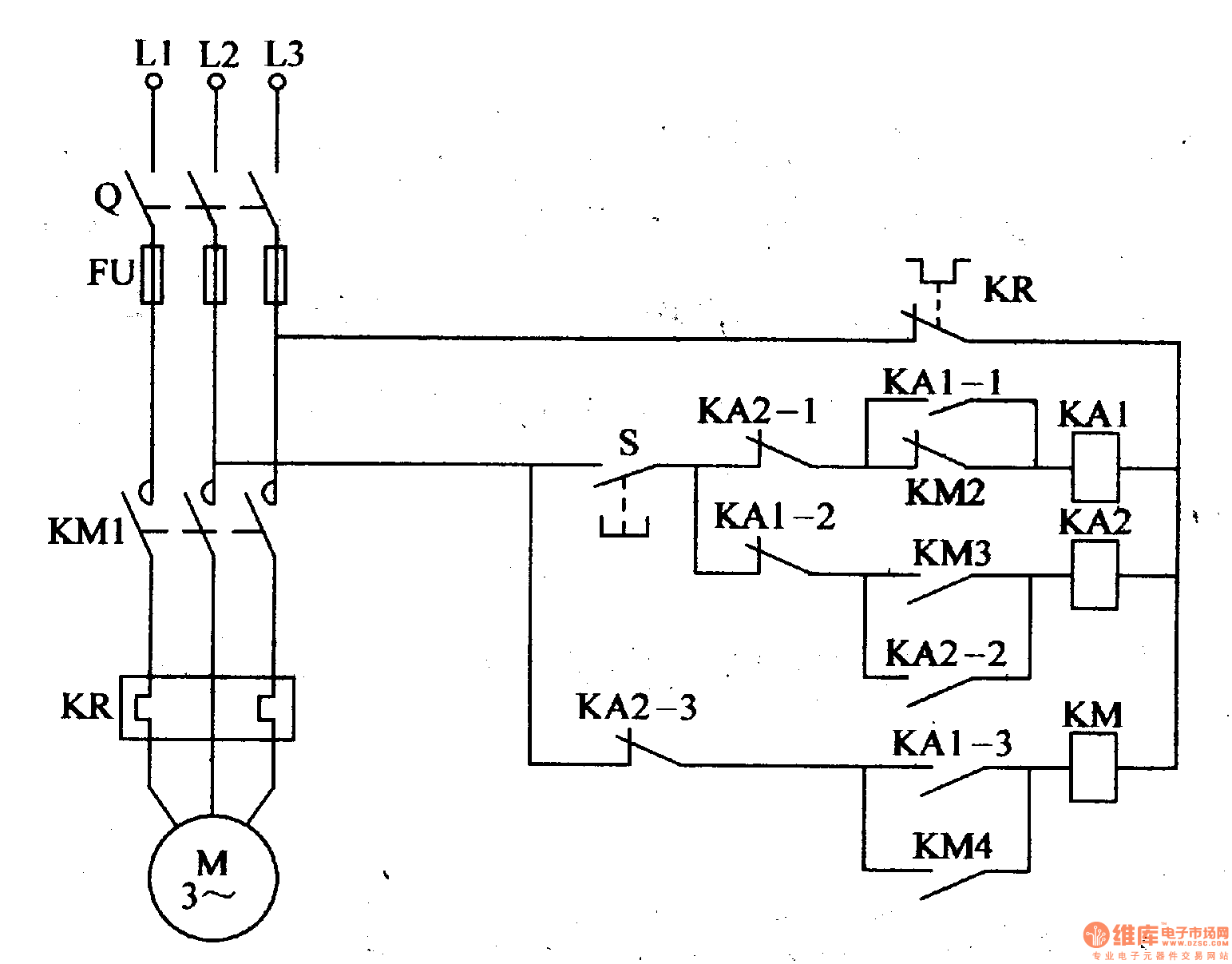
Figure 1 is a typical wiring diagram for a three phase magnetic motor starter. The dol starter consist a mccb or circuit breaker contactor and an overload relay for protection. A wiring diagram gives the necessary information for actually wiring up a group of control devices or for physically tracing wires when trouble shooting is necessary. Variety of motor control panel wiring diagram. In the above one phase motor wiring i first connect a 2 pole circuit breaker and after that i connect the supply to motor starter and then i do cont actor coil wiring with normally close push button switch and normally open push button switch and in last i do connection between capacitor. The simplest form of motor starter for the induction motor is the direct on line starter.
Basic wiring for motor control technical data. In the diagram i connect the incoming three phase supply l1 l2 l3 to the mccb circuit breaker molded case circuit breaker. Star delta y δ 3 phase motor starting method by automatic star delta starter with timer. An example of a wiring diagram for a motor controller is shown in figure 1.
