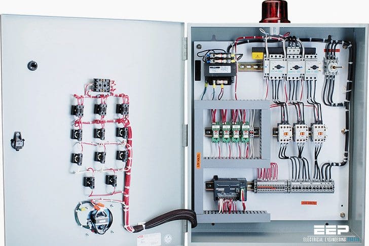
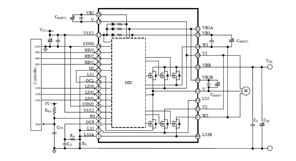
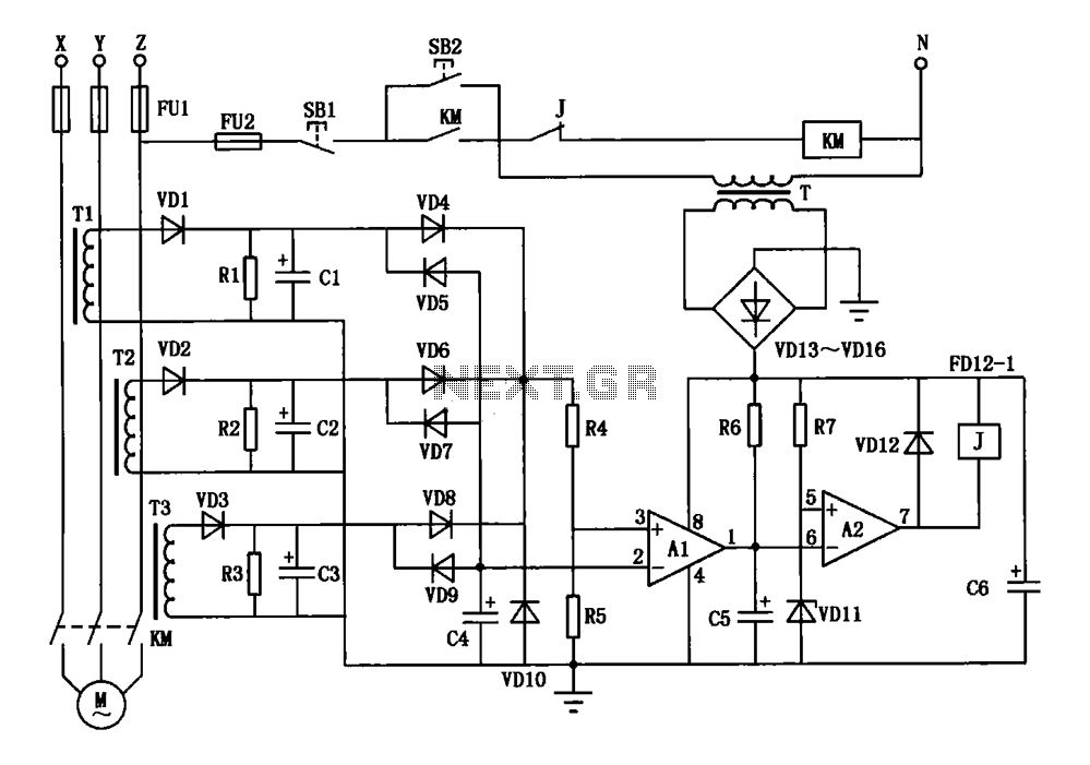
2 phase and 3 phase size 00 to 5 44 3 phase size 6 45 3 phase size 7 46. Basic wiring for motor control technical data.
Forward Reverse Motor Control Diagram For 3 Phase Motor
3 phase motor control panel wiring diagram. Ryb electrical 86679 views. Multi speed 3 phase motor 3 speeds 1 direction power control diagrams one line diagram of simple contactor circuit. We use 2 magnetic contactors as forward reverse switch. 33 l1 l2 l3 n suggested wiring arrangement selector switch hi speed contactor overload overload lo speed contactor these diagrams are current at the time of publication check the wiring diagram supplied with the motor. Refer to the motor manufacturers data on the motor for wiring diagrams on standard frame ex e ex d etc. Water pump controller with float switch duration.
They can be used as a guide when wiring the controller. 3 phase dol starter control and power wiring diagram. I have a conveyor from ground to first floor where would i add the forward and reverse and e stop buttons for the first floor on this diagram. Three phase motor connection reverse and forward power and control wiring diagrams. Figure 1 typical wiring diagram. How does a 3 phase induction motor start.
Motor 3ct to 120 v separate control ot is a switch that opens when an overtemperature condition exists type mfo. In the diagram i connect the incoming three phase supply l1 l2 l3 to the mccb circuit breaker molded case circuit breaker. Wiring diagram parts list design worksheet duration. Here i showed the forward reverse wiring diagram. This video gives a brief explanation on how a three phase motor control circuit works. They show the relative location of the components.
Wiring diagram book a1 15 b1 b2 16 18 b3 a2 b1 b3 15 supply voltage 16 18 l m h 2 levels b2 l1 f u 1 460 v f u 2. Figure 1 is a typical wiring diagram for a three phase magnetic motor starter. Why we called a single phase submersible motor a 3 wire submersible that we also know that we have two wire in single phase power supply. Today i am hear to write about submersible pump control box wiring diagram in this post you will complete understood about 3 wire submersible pump wiring diagram which is an single phase submersible pump motor. Three phase electrical wiring installation in home iec nec. Forward reverse motor control diagram for three phase motor for three phase motor forward reverse control circuit.
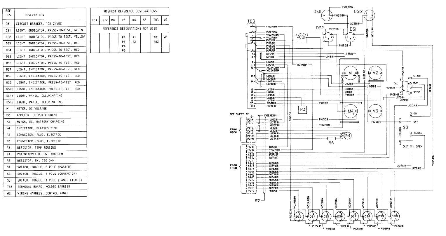
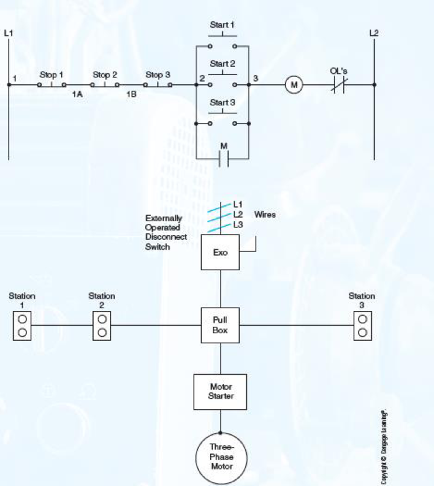
Show the control circuits only power circuits are omitted for clarity since they can be traced readily on the wiring diagrams heavy lines. A wiring diagram gives the necessary information for actually wiring up a group of control devices or for physically tracing wires when trouble shooting is necessary.


