In the presence of a human ir radiation the sensor detects the radiations and instantly converts it into minute electrical pulses enough to trigger the transistor into conduction making. The first pir circuit diagram for sensing moving humans is shown above.
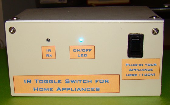
A Very Simple Ir Remote Control Switch For An Electrical
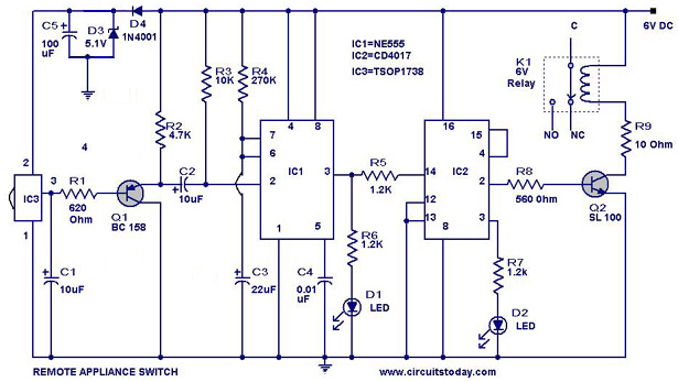
Ir switch circuit diagram. Nowadays security is the first and foremost requirement of everyones life. So it works like a toggle switch. Because q2 is connected to the reset pinpin 15 of 4017 it will reset the ic and again output at q 0zero becomes high and q 2 becomes low initial state. This is the very simple circuit diagram of ir remote control switch. We uses normal switch in our daily life and after a long time used to these swithing system we can no more interested in that. A 100uf capacitor is connected across the supply to provide the constant supply to the circuit without any ripple.
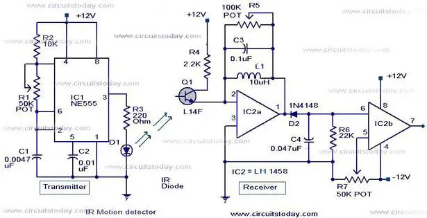
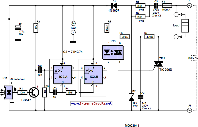
With the given values output of ic1 remains low for three minutes. Ir sensor is very popular sensor which is used in many applications in electronics like it is used in remote control system motion detector product counter line follower robots alarms etc. Output pin 3 of the 555 timer ic has been connected to ir led using 470 resistor and a push button switch. Circuit diagram of infrared remote control switch. This is a good solution for a unique and so interesting idea to wireless switching system to control the home appliance. This is a schematic circuit diagram of a remote controlled switch for home appliances.
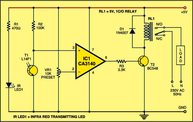
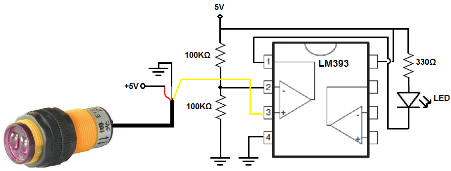
It is more reliable than the popular timer ic 555. Here the ic1 is wired as a short duration monostable timer using r3 and c1 as timing components. In this circuit there are two relays are used the first relay is used for giving input signal. An above image is an infrared proximity sensor circuit diagram. This circuit works with any infrared remote using for tv dvd usb player etc. Along with the pir sensors a simple circuit is used with it.
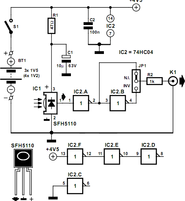
Ir receiver circuit diagram. Tsop1738 used in the circuit for detecting ir signals from the remote. Cd4538 is the precision monostable astable multivibrator ic that is free from false triggering. The circuit is simple and easy to make it has 2 transistors 4 resistors an ir led an ir phototransistor and a purple or white or green led use as an indicator so you can remove it if you want. Ir sensor basically consist an ir led and a photodiode this pair is generally called ir pair or photo couplerir sensor work on the principal in which ir led emits ir radiation and photodiode sense. Ir switch circuit diagram.
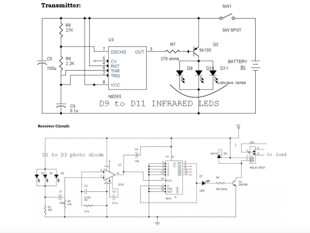
A practical implementation of the explained pin out details can be witnessed here. Ir remote control circuit diagram. In this article we will be discussing a very useful and reliable security device called infrared motion detector circuitthe circuit can be used for detection of moving object or body with the use of infrared sensors like ir pir etc. Whenever we press the button circuit emits modulated ir at 38 khz. This will deactivate the relay and switch off the light. This current is given to the inverting input of 3130 ic which will get triggered by this current and give amplified output.
In the receiver section there are 3 photodiodes which will detect the infrared signals from the receiver and produce leakage current to the capacitor c1.


