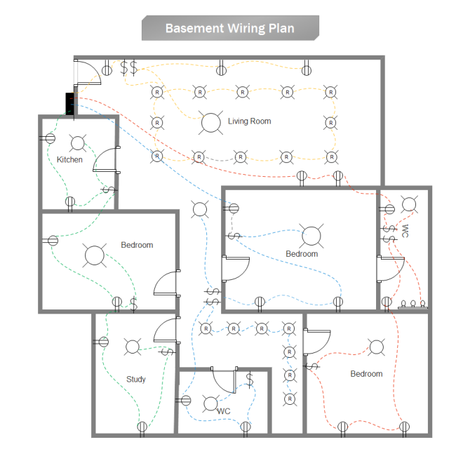
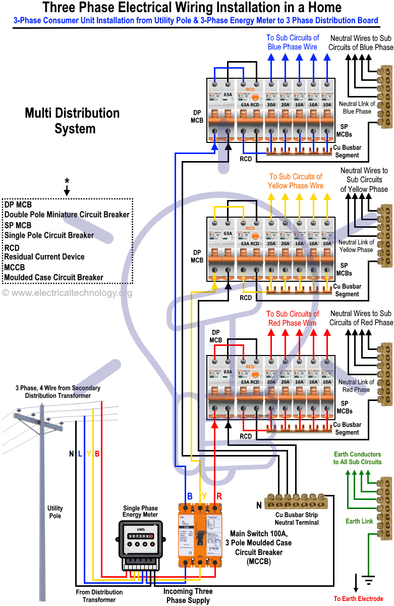
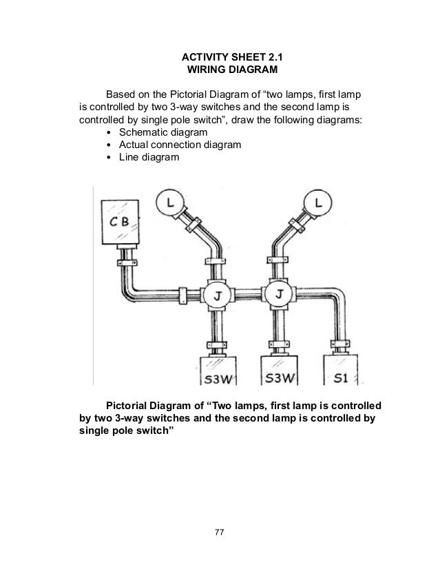
It helps locate the incoming service. An electrical drawing is a type of technical drawing that shows information about power lighting and communication for an engineering or architectural projectany electrical working drawing consists of lines symbols dimensions and notations to accurately convey an engineerings design to the workers who install the electrical system on the job.

How To Construct Wiring Diagrams Industrial Controls
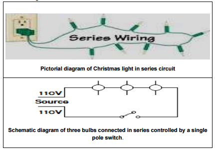
Interpret electrical wiring plan. Using layers to create electrical plans. To read electrical schematics the fundamental electrical schematic symbols should be understood. A schematic shows the plan and function for an electrical circuit but is not concerned with the physical layout of the wires. The physical locations of. You now have a separate layer on which to build your electrical plan. Circuit drawings and wiring diagrams description successfully performing electrical work requires the ability to read and interpret many different types of drawings and diagrams.
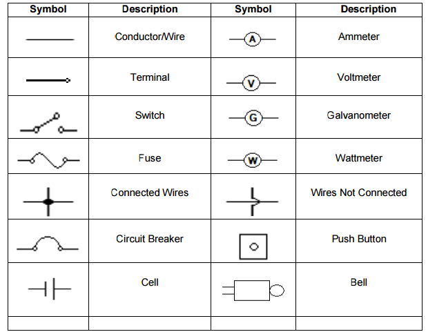
Identify the steps in the electrical design process. Electrical plans are also used for estimating installation and material costs. Recognizing electrical schematic symbols here are some of the standard and baisc symbols for various components for electrical schematics. How to read a electrical drawing 1. It shows where and how the conductorsconduits are to run. Interpret the various components of an electrical plan including general and specialized loads lighting systems and distribution systems.
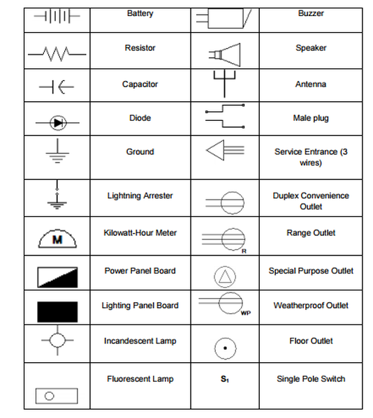
This plan is drawn to scale with the exception of the various electrical symbols which must be enlarged to be readable. Understanding circuit symbols and components is another one. A lamp is usually represented as a circle with a cross inside it. Recognize the symbols used in electrical plan design. The electrical layoutplan determine where each electrical device and piece of equipment is to be located related to the architectural features of the area. Just open your floorplan and under the page tab choose layers new layer.
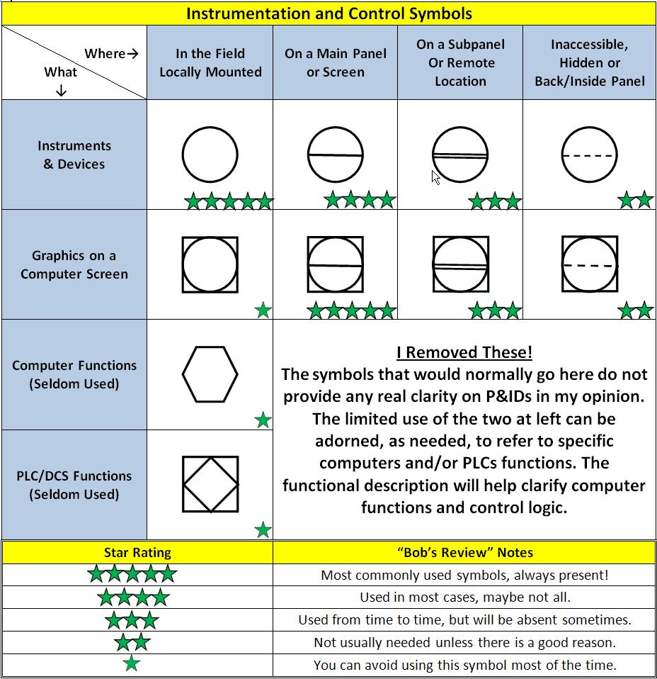
Using the basic electrical floor plan and the symbol chart on the following pages explain the. Name the new layer. It indicates the position of electrical fixtures such as convenience outlets switches lightings door bells and others to be installed. Floor plans showing the walls and partitions for each floor level. Then well talk about how those symbols are connected on the schematics. Familiarize with standardized electrical symbols knowing the meanings of basic electrical symbols in your electrical drawing will help you quickly understand and troubleshooting the circuit.
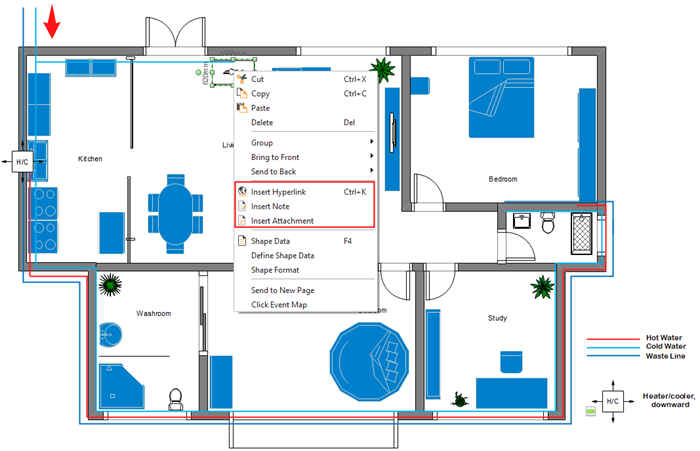
Wiring diagrams show how the wires are connected and where they should located in the actual device as well as the physical connections between all the components. You can easily create detailed electrical plans by overlaying electrical symbols on a floorplan. A complete set of working drawings for. Electrical plan is a graphical presentation of electrical wiring connections to install in a particular house or building. Plot plan showing the location of the building on the property and all outside electrical wiring including the service entrance. Determine the scope of an electrical design project.
When the current passes through the lamp it will produce light.


