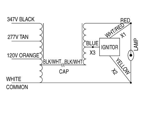
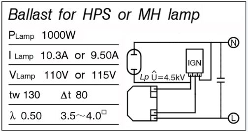
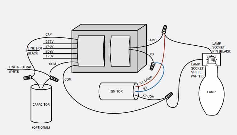
Test the input voltage and output voltage of the ballast transformer. To view a larger image of the diagram click on the thumbnail.
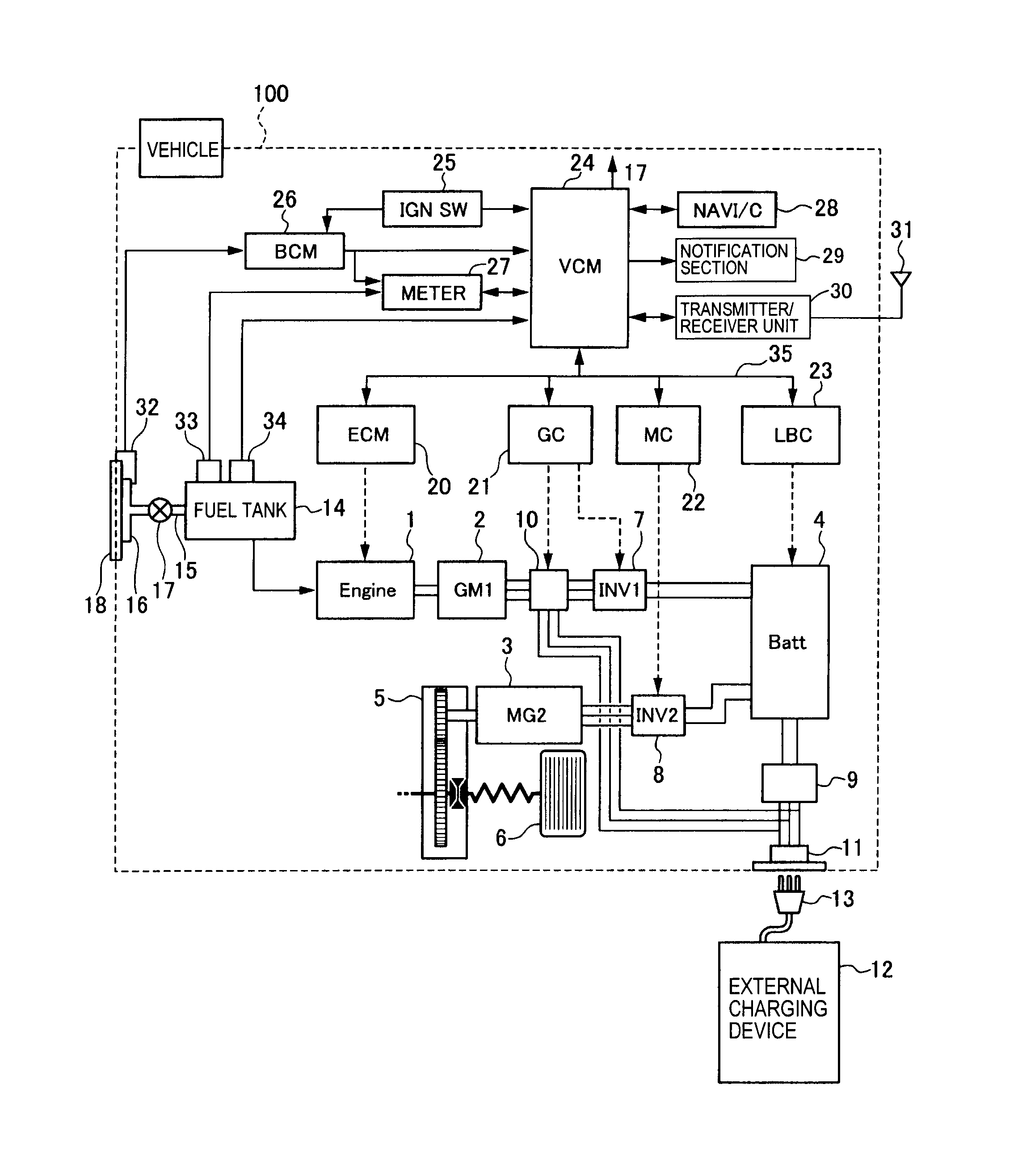
Diagram Based 480 Volt Metal Halide Wiring Diagram
Hps ballast wiring diagram. Variety of philips advance ballast wiring diagram. It reveals the parts of the circuit as streamlined forms and the power and signal links between the gadgets. Ballast installations and groundings should be made in accordance with all applicable government codes and regulations where required. A wiring diagram is a simplified standard photographic depiction of an electric circuit. Test the capacitor for proper storage capacity. Therefore there is a need for a 14 gauge wire wire nuts power cord and male plug set.
Electrical wiring diagrams v metal halide w hps x px image size for wiring diagram for metal halide ballast. A wiring diagram is a streamlined conventional photographic representation of an electric circuit. I also have these for sale in the us for 75 including shipping. Collection of high pressure sodium ballast wiring diagram. A very first appearance at a circuit diagram could be confusing however if you could review a subway map you can check out schematics. If the windings show any sign of burning replace the ballast.
High pressure sodium ballast wiring diagram a beginner s overview of circuit diagrams. This video is about wiring a venture 1000w hps core and coil ballast for demonstration purposes only. Hps imperator machine tool industrial control transformers. Uni form standard metal halide hps and remote. Typically if the capacitor is not physically damaged or leaking oil it is in good shape. Check the manufacturers specifications for wiring diagrams and voltages.
Also obtain a wiring diagram for the ballast. Hps wiring diagram industrial control transformer wiring diagrams hps the hps imperator series of machine tool industrial molded control transformers are available in many standard offerings this wiring hook up instruction sheet. Hps offers instruction sheets to assist you in the proper installation and operation of your hps product. In addition to these three the hps ballast should also be wired to a bulb and socket. Select wiring diagrams for these ballast types. Step 2 wire the internal parts.
It reveals the elements of the circuit as simplified shapes as well as the power as well as signal links between the devices. Each component should be set and linked to other parts in specific manner. Mh ballast wiring diagram 100w mh ballast wiring diagram 150w mh ballast wiring diagram 400w mh ballast wiring diagram every electrical structure consists of various different pieces. This usually comes in the manual or written on the ballast enclosure. If not the arrangement wont work as it ought to be.


