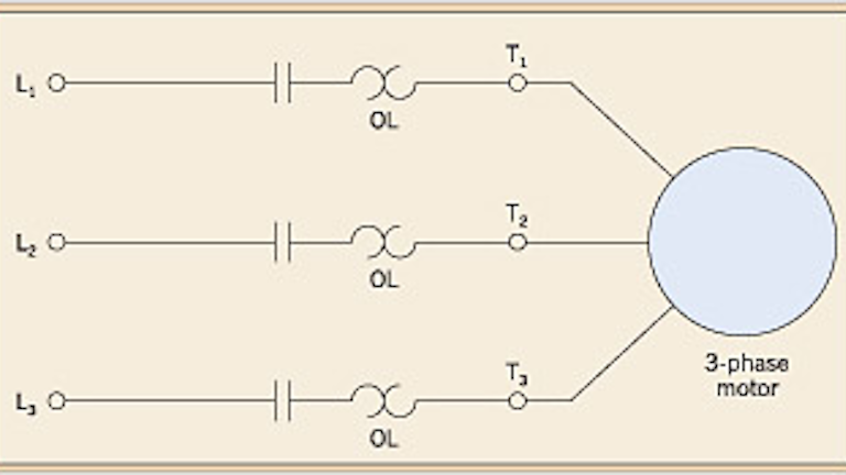
Line voltage control three phase 3ph motor starter controlling a three phase motor rev 08 aug 2006 the above wiring diagram assumes your magnetic starter has a 240v coil. Assembly your own direct on line motor starter.

Motor Control Circuits Types Electrical Industrial
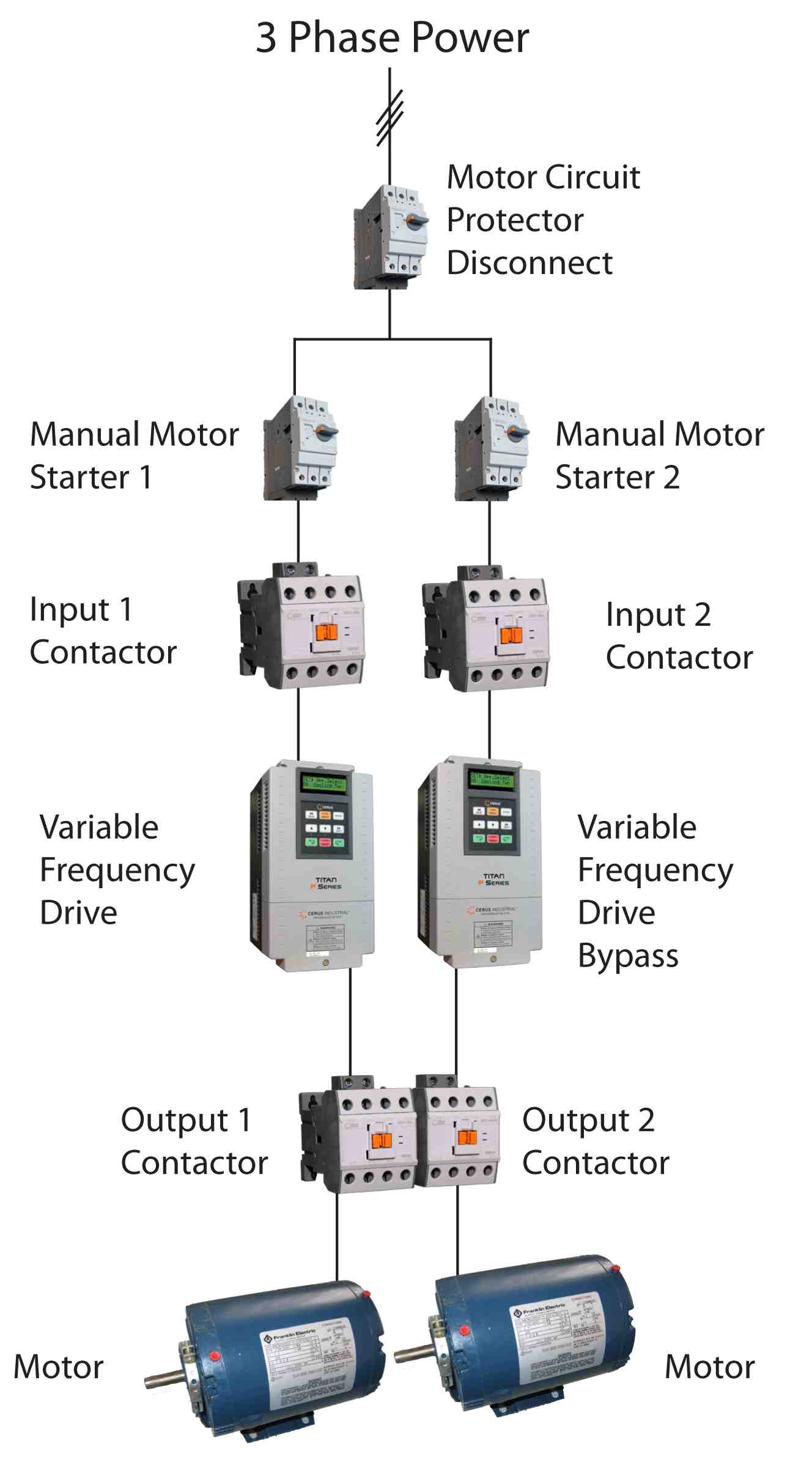
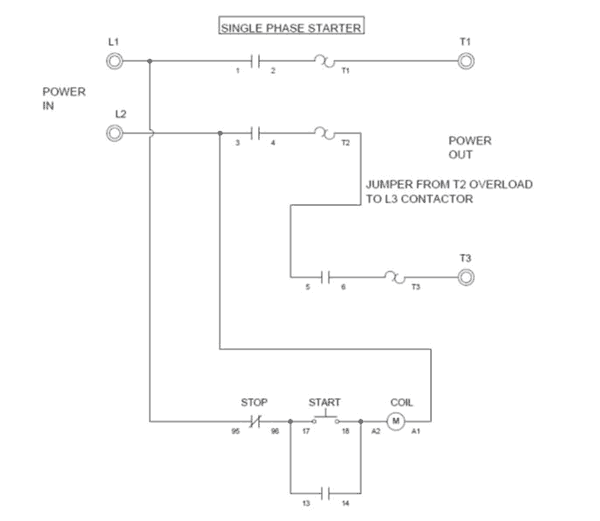
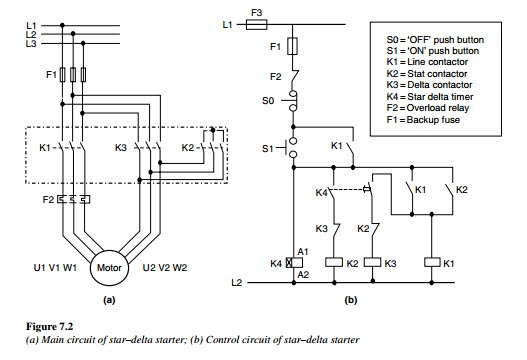
3 phase motor starter with overload protection wiring diagram. The following diagram is shown for 3 phase motor control of a delta star connection. Previously we discussed what a magnetic motor. The above diagram is a complete method of single phase motor wiring with circuit breaker and contactor. Single phase motor starters are not commonly available since this is a rare case and with a little bit of know how a 3 phase motor starter can easily be wired for single phase power. Three phase motor connection schematic power and control wiring installation diagrams. These two buttons ie.
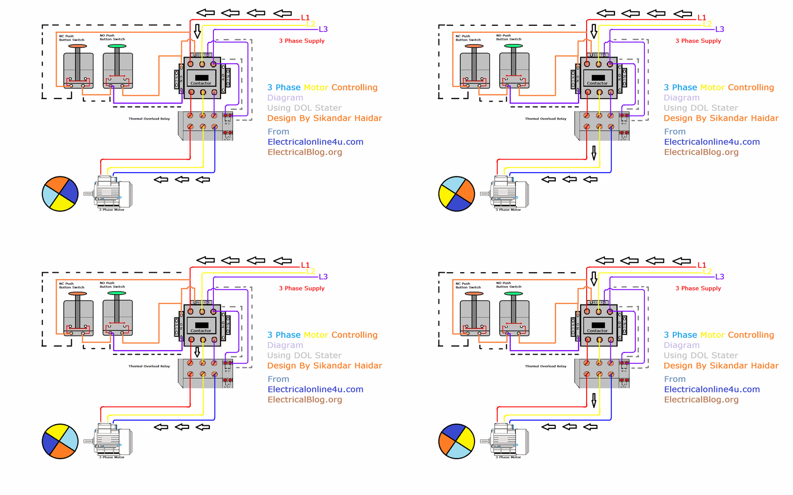
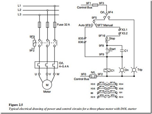
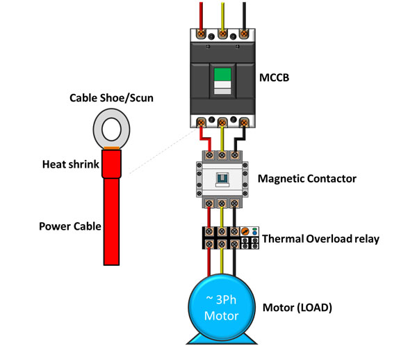
In the above one phase motor wiring i first connect a 2 pole circuit breaker and after that i connect the supply to motor starter and then i do cont actor coil wiring with normally close push button switch and normally open push button switch and in last i do connection between capacitor. The simplest form of motor starter for the induction motor is the direct on line starter. As a result of this if a single phase supply is wired such that line and neutral pass through just 2 of the 3 elements the overload can trip. The dol starter comprises of an mccb or circuit breaker contactor and an overload relay for protection. Single phase motor overload protection. The wiring diagram for a dol stater is shown below.
Like subscribe and dont skip the ads facebook subscribe our page to. Step by step guide how to wire contactor and motor protection switch. A direct online starter consits of two buttons a green button for starting and a red for stopping purpose of the motor. All connection i shown with complete guide. Wye delta open transition 3 phase motors. Star delta y δ 3 phase motor starting method by automatic star delta starter with timer.
In the above three phase dol starter wiring diagram. To avoid this problem when using a standard overload with a single phase motor load the wiring through the overload must be arranged so that all three elements are in the circuit. It uses three contactors an overload relay one auxiliary contact block a normally open start pushbutton a normally closed stop pushbutton an on delay timer of 0 20 seconds and a power supply with a fuse. Three phase motor connection stardelta without timer power control diagrams. Green and red or start and stop buttons. The dol starter consist a mccb or circuit breaker contactor and an overload relay for protection.
If you have a 120v coil instead of running a line from coil overload l2 you must run coil overload neutral. In the below dol starter wiring diagram i shown a molded case circuit breaker a magnetic contactor normally open push button normally close push button switch thermal overload relay motor trip indicator and 3 phase motor. This is how springer controls does it in our ul508a certified panel shop.
