It means all the connected loads to the load terminals of gfci are protected. Your cable should be long enough to reach each socket.
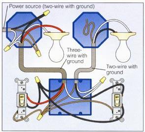
Wiring A 2 Way Switch
How to wire a switch off an outlet diagram. As discussed before gfci also known as ground fault circuit interrupter is a protection device against electric shock which detects the ground faults and leakage currents especially in outdoor and watery areas such as bathroom kitchen laundry etc. Connect the last switch in the usual manner looping the wire around the screw in a clockwise direction. To connect the switches simply score the wire with your wire stripper and push the insulation to expose about 34 in. You should switch off electrical power from the mains to avoid electrocution. Here a receptacle outlet is controlled with a single pole switch. Switch off the mains.
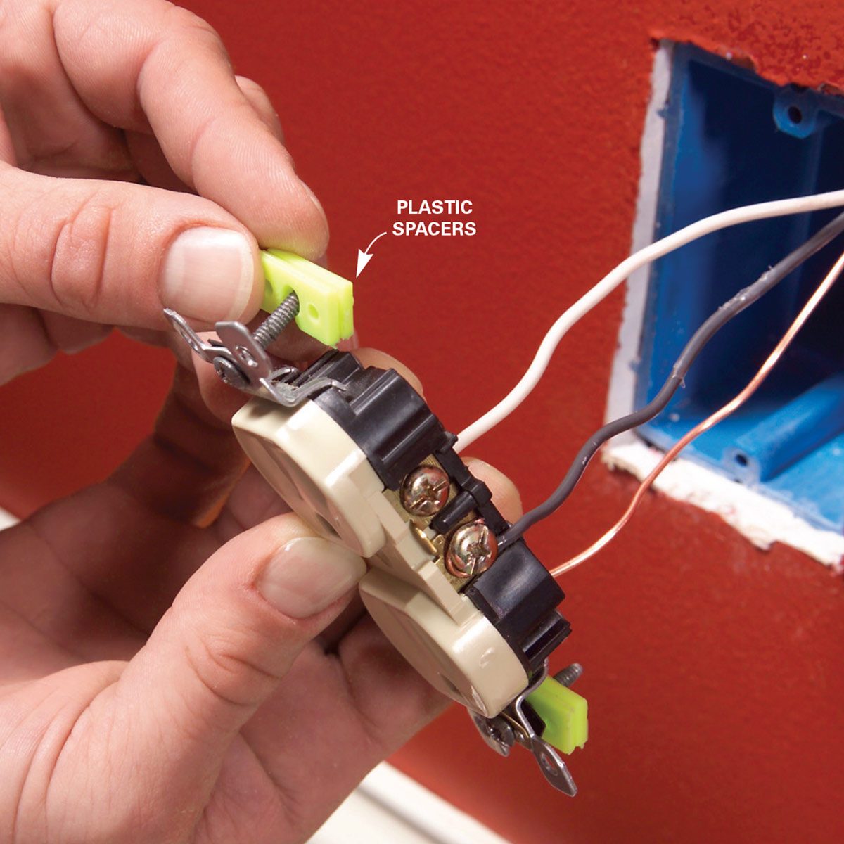
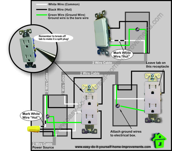
The source is at the outlet and a switch loop is added to a new switch. The toggle switch in the combo switch outlet controls the first light bulb while the single way. 12 9 17 its over 9000. The source is at sw1 and the hot wire is connected to one of the terminals there. Notice that these outlets have the tab removed from the hot side or brass side of the outlet which allows the top half of the plug to be controlled only from the switch. Run the cable from the circuit breaker to the location of the electrical outlet.
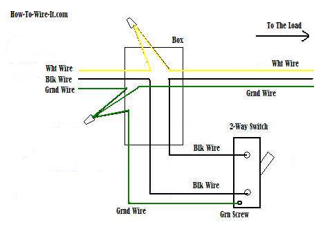
One switch screw terminal is for the power in. How to wire an electrical outlet. The black wire from the switch connects to the hot on the receptacle. One cant be too careful. In this diagram 2 wire cable runs between sw1 and the outlet. When wiring a switch to control a 110volt outlet the power wire is connected to the switch as follows.
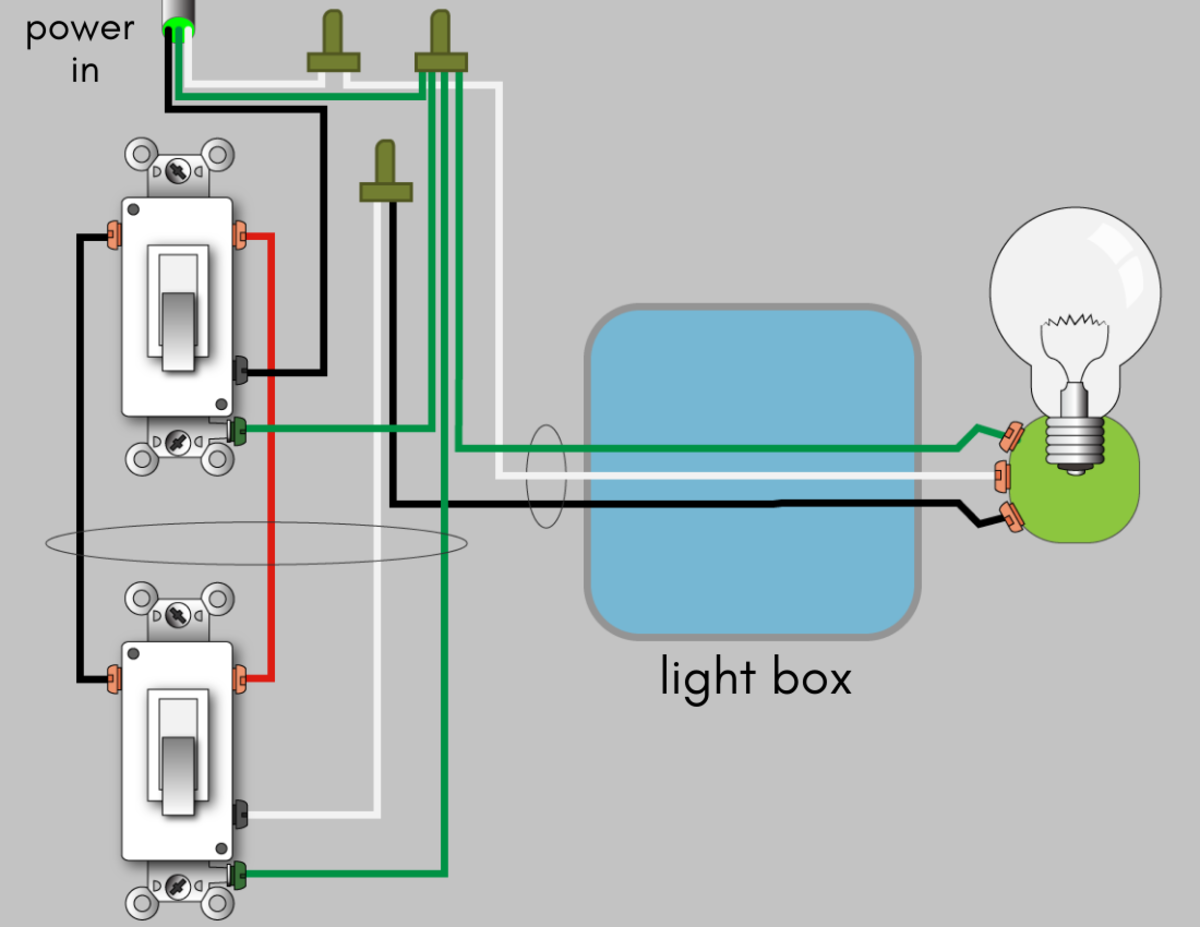
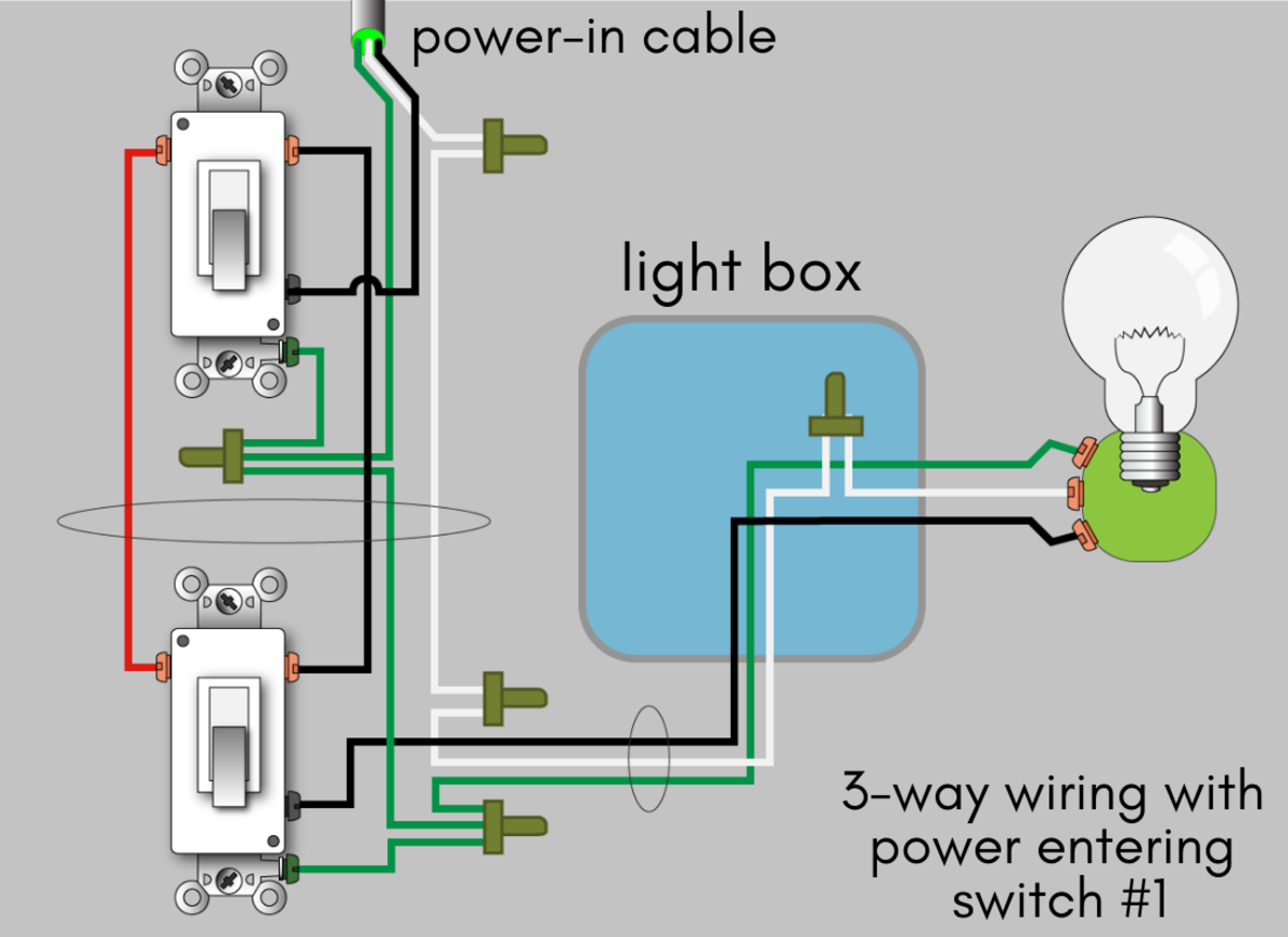
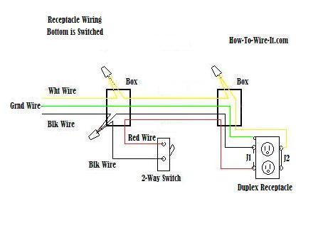
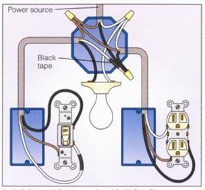
This is commonly used to turn a table lamp on and off when entering a room. In this video we learn how to wire a half hot receptacle which is useful if you want to control an outlet with a light switch. The diagram below shows the power entering the circuit at the grounded outlet box location then sending power up to the switch and a switched leg back down to the outlet. This wiring diagram illustrates adding wiring for a light switch to control an existing wall outlet. Instead of running a separate pigtail from the hot wire to each switch just leave the hot wire extra long. Outlets are split wired so that the top half of the receptacle is live all of the time and the bottom of the receptacle is controlled by the wall switch.
How to wire a switch for an outlet keep in mind that when wiring a switch it is not necessary to switch the white neutral wire. In this gfci outlet wiring and installation diagram the combo switch outlet spst single way switch and ordinary outlet is connected to the load side of gfci. Wiring a switch to a wall outlet. One switch screw terminal is for the power out. The hot source wire is removed from the receptacle and spliced to the red wire running to the switch. Gfci combo switch and outlet wiring circuit diagrams and installation.
Half switched outlet wiring diagram depicting the electrical power feeding into an electrical receptacle box and then going to a switch and to another receptacle.
