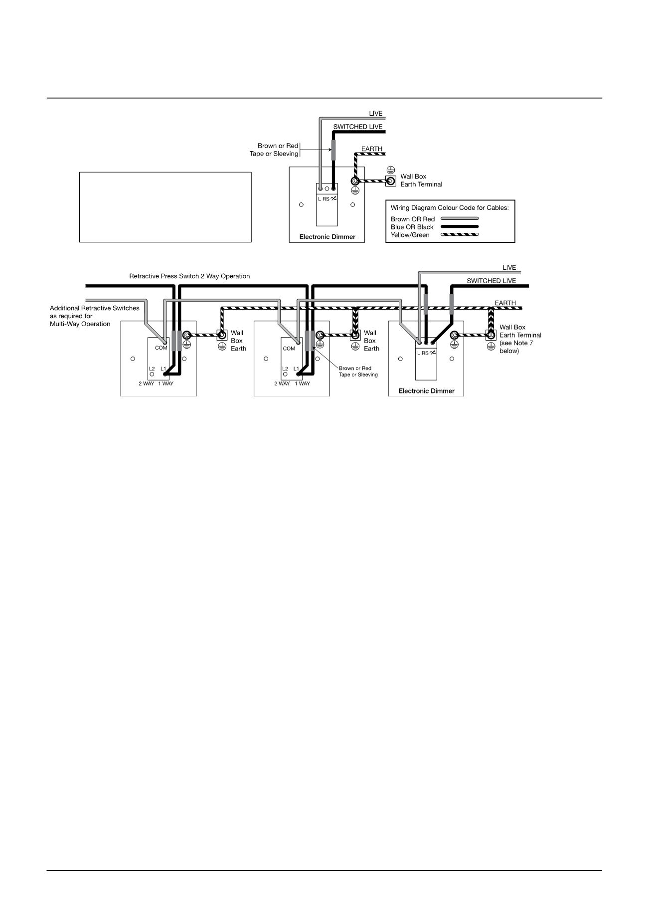
This video also shows how an intermediate switch works. This diagram shows the first wiring option for this device.
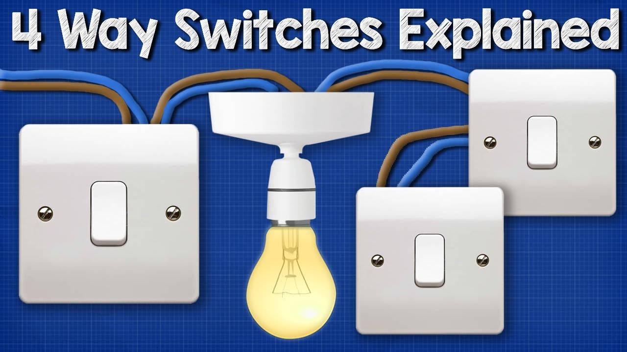
Wiring A 4 Way Switch
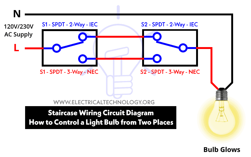
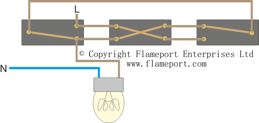
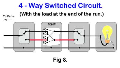
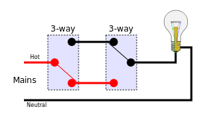
How to connect intermediate switch diagram. If we connect an intermediate 4 way switch in between two 3 way switches in the above circuit we will be able to onoff the water heater from three different places as shown in below wiring diagram for 240v 230v and 120v ac. Check here to see wiring diagrams for a gfci outlet switch combo when you need a device like this with ground fault protection in a kitchen bathroom or laundry room. In some countries the four way is called an intermediate switch. This is the new method to make a 2 way switching connection as it is slightly different from the two wire control method. On the other hand when knob is down terminal a is connected to terminal b and c to d then. Intermediate switches can be used for 1 and 2 way switching.
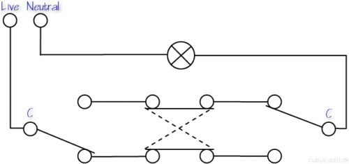
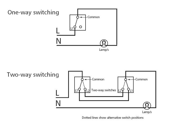
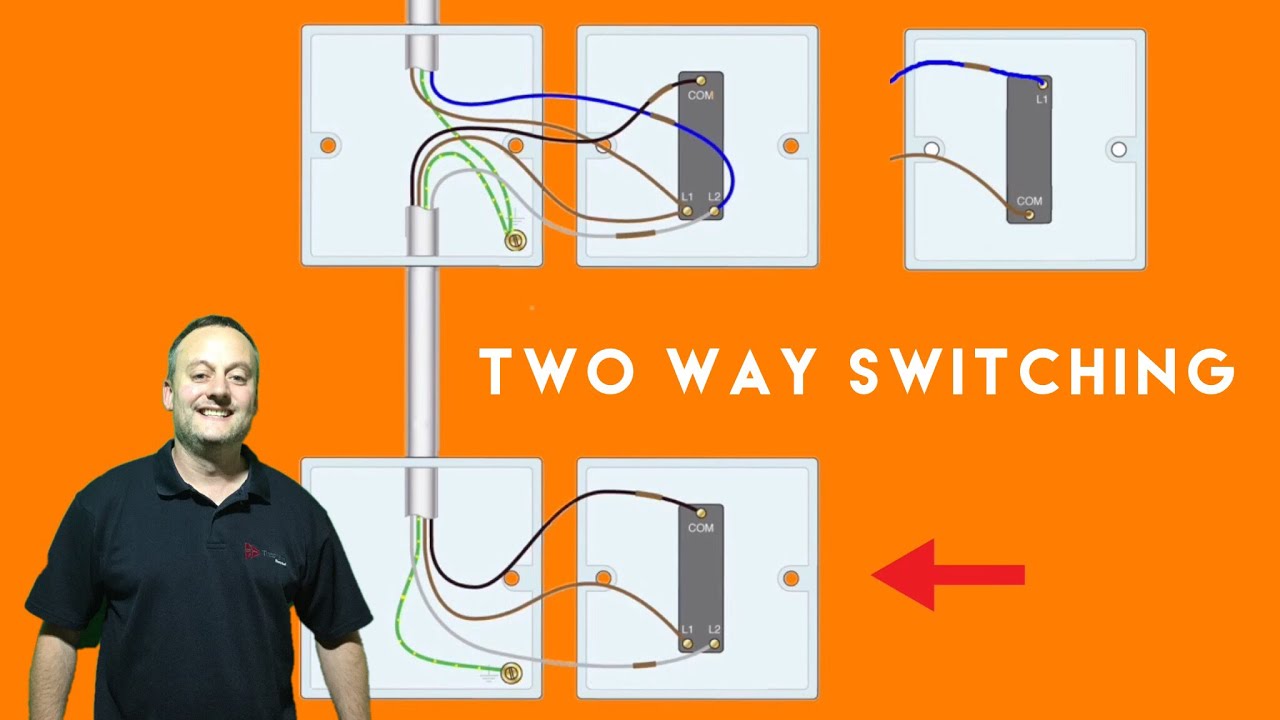
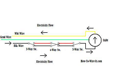
To wire a three way lighting circuit you will need 2 two way switches and an intermediate switch. In a previous video i showed how a two way. Controlling of water heater from three places using two 3 way four way switch. What is intermediate switch how it works. In this arrangement the connecting tab between the hot terminals remains intact. The circuit consists of a two way switch at each end top and bottom switches in fig 2 and an intermediate switch in the middle.
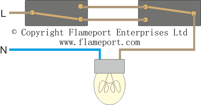
All three switches are connected together by a three core and earth control cable. The diagram shows the common method of wiring an intermediate switch into a two way light switch circuit. When the switch knob is up the terminal contacts of intermediate switch connect terminal a with terminal c and terminal b with terminal d as shown in fig 1a. You would just continue from one 3 way switch box with the 143 three conductor cable two colored traveler wires a white neutral and a bare or green ground wire in and out of each four way switch box. If replacing an existing switch note the location of the terminals and the colour and position of cable connections. The white wires get spliced through.
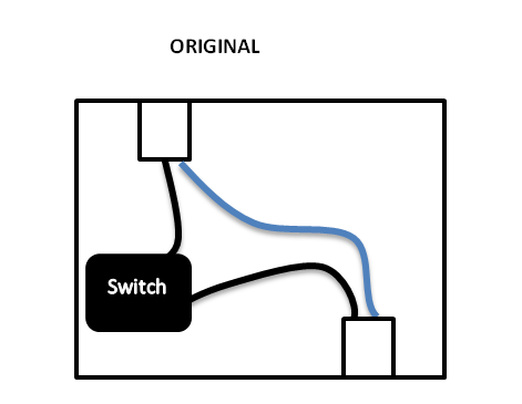
How to connect 2 way switch wiring using three wire control. Where 0 represents the off condition and 1 represents the on condition. Notice that the wire connected to the com terminals is looped straight through the intermediate switch using a cable connector. This method is commonly used now days as it is efficient than the two wire control system.
Gallery of How To Connect Intermediate Switch Diagram