The diagonal of that parallelogram shows the vector difference of i r and i b which is equal to current in line 1 i 1. One disadvantage of delta connected three phase transformers is that each transformer must be wound for the full line voltage in our example above 100v and for.
Wye Delta Connection
Y delta connection diagram. Often the connection will depend on the manufacturing process. For example the wye connection requires fewer turns than the delta connection 17322 to achieve the same electrical characteristics. The current of line 1 can be found by determining the vector difference between i r and i b and we can do that by increasing the i b vector in reverse so that i r and i b makes a parallelogram. In a delta connected dd group of transformers the line voltage v l is equal to the supply voltage v l v sbut the current in each phase winding is given as. Initially we explored the idea of three phase power systems by connecting three voltage sources together in what is commonly known as the y or star configuration. This configuration of voltage sources is characterized by a common connection point joining one side of each source.
1 3 i l of the line current where i l is the line current. Line phase current and line phase voltage in delta δ connection. The deltawye connection is the most commonly used three phase transformer connection. Relation between phase current and line current in delta connection. The wye connected secondary allows single phase load to be distributed among the three phases to neutral instead of being placed all on one winding as with a four wire delta secondary. In this article wye star and delta connection is discussed with respect to line line line neutral voltages and currents.
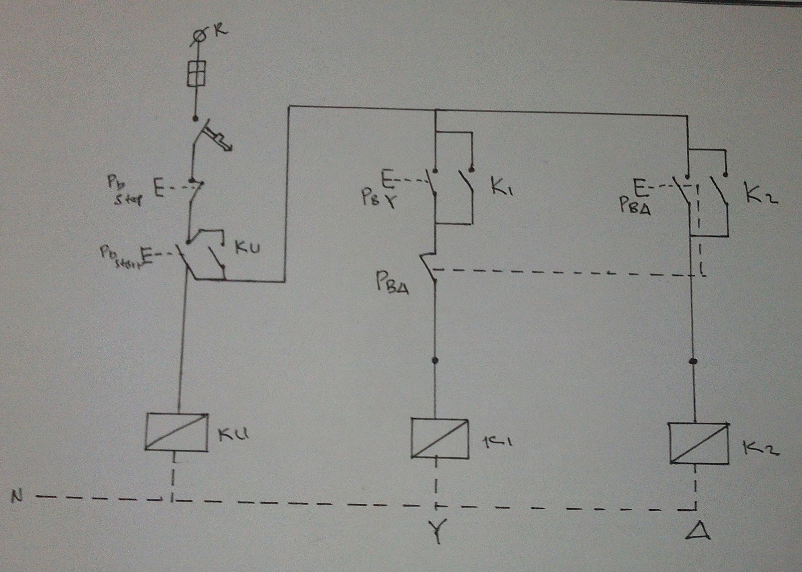
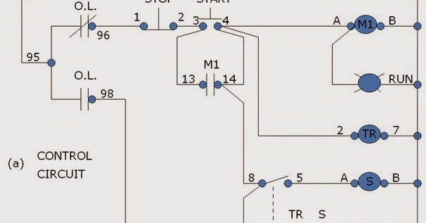
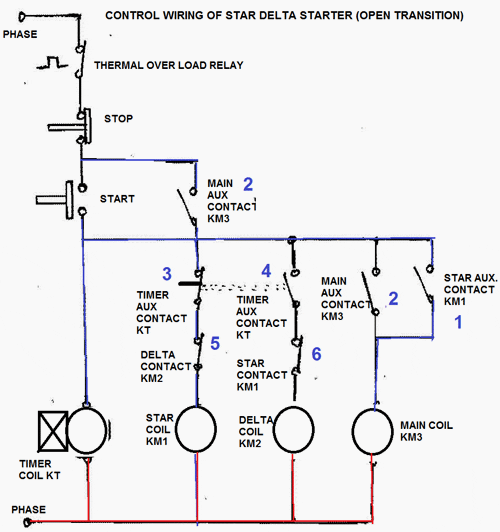
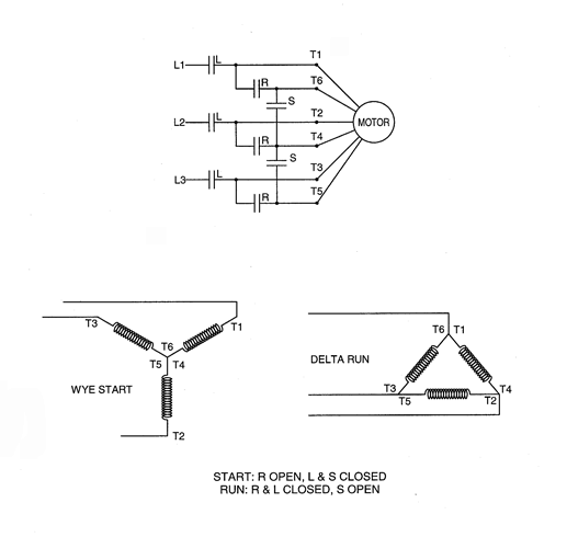
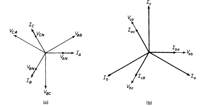
Wye and delta connection vector diagram. The y δ transform also written wye delta and also known by many other names is a mathematical technique to simplify the analysis of an electrical networkthe name derives from the shapes of the circuit diagrams which look respectively like the letter y and the greek capital letter δthis circuit transformation theory was published by arthur edwin kennelly in 1899. Collection of wye start delta run motor wiring diagram. A wiring diagram is a simplified conventional photographic depiction of an electrical circuit. To obtain the delta connections a 2 is connected with b 1 b 2 is connected with c 1 and c 2 is connected with a 1 as shown in the above figure. Although the wye and delta connection diagrams are quite simple the actual motor windings are far more complex.
It shows the parts of the circuit as streamlined forms as well as the power as well as signal links between the gadgets. December 29 2018 admin power quality delta connection star connection wye connection. Additionally the vector phase angles between delta and wye connection is also discussed. The three conductors r y and b are running from the three junctions known as line conductors.

