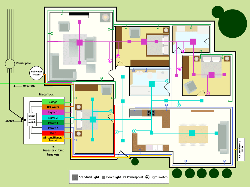
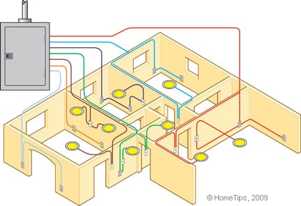
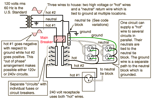
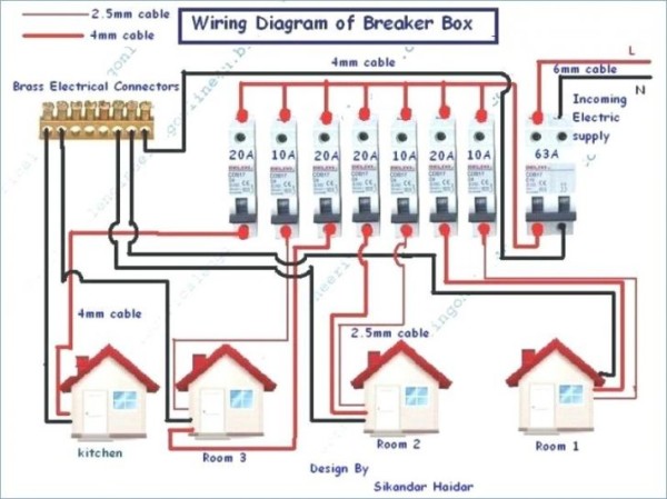
In a typical new town house wiring system we have. The image below is a house wiring diagram of a typical us.
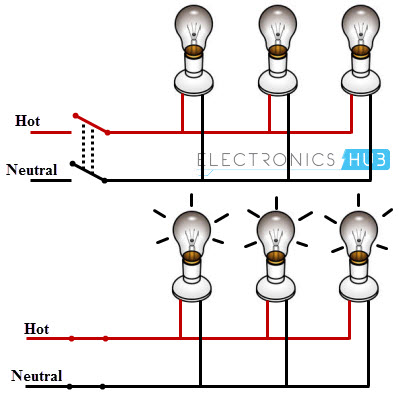
Parallel Electrical Circuit Wiring Diagram Fiatertu Rpg3
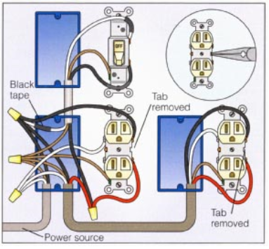
House electrical circuit diagram. It shows the components of the circuit as simplified forms and also the power and also signal links in between the tools. Electricity travels in a circle. The other half in the case of a 120 volt circuit is the neutral wire. Typical house wiring diagram illustrates each type of circuit. Circuit breaker wiring diagrams wiring for a breaker box a gfci breaker as well as 15 20 30 and 50 amp circuit breakers. Or canadian circuit showing examples of connections in electrical boxes and at the devices mounted in them.
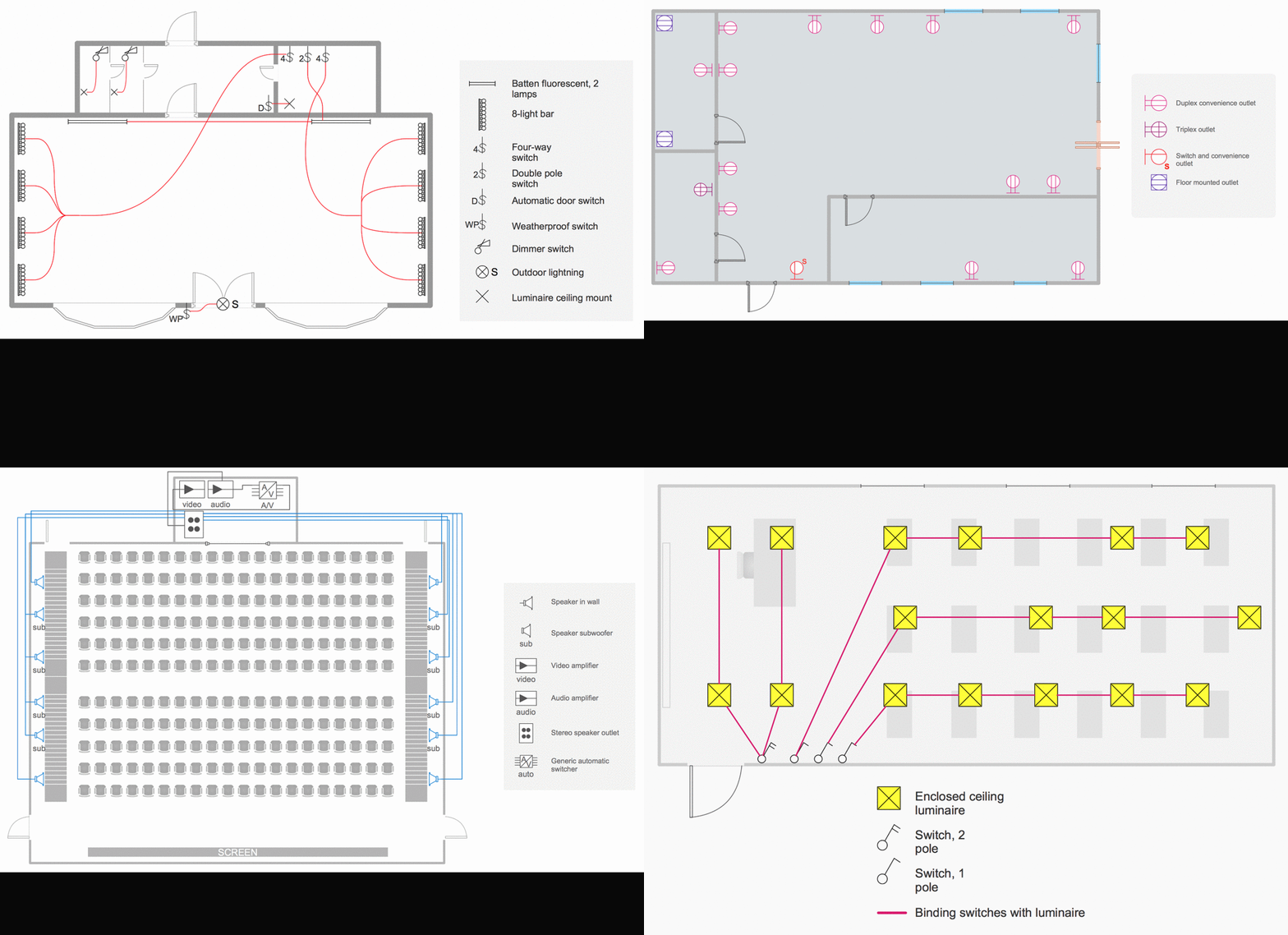
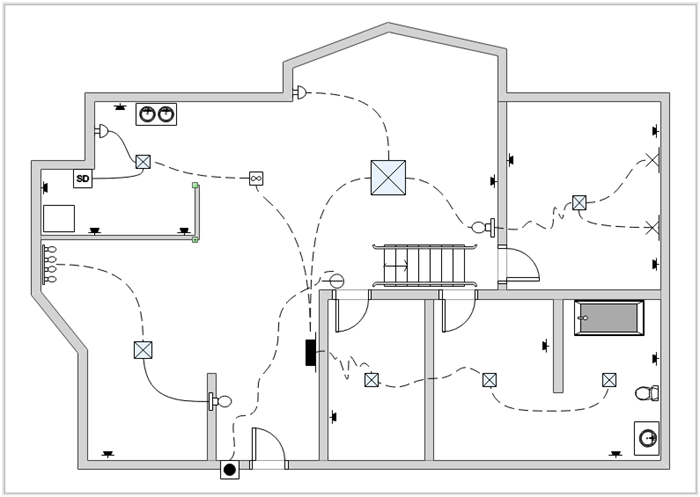
It moves along a hot wire toward a light or receptacle supplies energy to the device called a load and then returns along the neutral wire so called because under normal conditions its maintained at 0 volts or what is referred to as ground. Wiring diagrams device locations and circuit planning a typical set of house plans shows the electrical symbols that have been located on the floor plan but do not provide any wiring details. This page takes you on a tour of the circuit. For a 240 volt circuit the other half is a hot wire from the other phase the other hot coming from the transformer. Switched receptacle wiring diagrams wiring diagrams for a switch to control a receptacle with various arrangements and multiple receptacles in the same circuit. The one line diagram is similar to a block diagram except that electrical elements such as switches circuit breakers transformers and capacitors are shown by standardized schematic symbols.
A one line diagram or single line diagram is a simplified notation for representing an electrical system. A split load cu. This information will help as an garage electrical wiring guide. A wiring diagram is a streamlined standard photographic depiction of an electric circuit. A circuits hot wire is we might say one half of the path the circuit takes between the electrical source and the operating items loads. 2 such rings is typical for a 2 up 2 down larger houses have more.
Variety of house wiring diagram pdf. In an electric power system switchgear is the combination of electrical disconnect switches fuses or circuit breakers used to control protect and isolate electrical equipment. Garage electrical wiring diagram this article will show you the home electrical wiring diagram for garages careful planning for your garage with immediate and future equipment considerations will help you understand how to size your electrical circuit requirements. Having a map of your homes electrical circuits can help you identify the source of a problem. Live neutral tails from the electricity meter to the cu. Figure 2circuit drawing line diagram.
Ring circuits from 32a mcbs in the cu supplying mains sockets. It is up to the electrician to examine the total electrical requirements of the home especially where specific devices are to be located in each area and.


