How to read an electrical diagram lesson 1 duration. Now if you have any question and have any suggestion then you can use the below comments box.

3 Phase Reversing Motor Wiring Diagram Automotiver 7
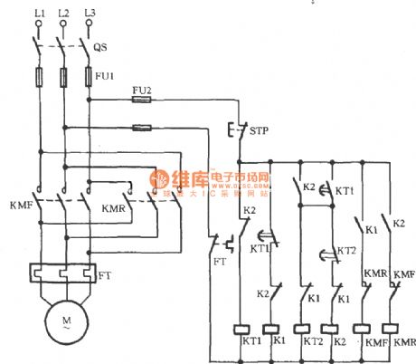
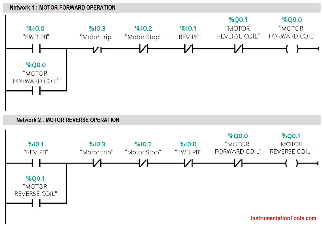
Forward reverse motor diagram. A wiring diagram is a simplified conventional pictorial representation of an electrical circuit. I hope you will share this post on social media. Figure 2 forwardreverse motor wiring diagram for simplicity the plc implementation of the circuit in figure 1 includes all of the elements in the hardwired diagram even though the additional starter contacts normally closed r and f in the hardwired circuit are not required since the push button interlocking accomplishes the same task. As the name defines forward reverse starter is used to run the motor in both sides forward and reverse. Forward reverse starter diagram. In this post i will gave you two three phase motor controlling diagram for forward reverse connection.
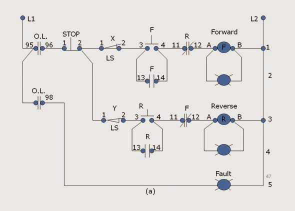
Variety of single phase motor wiring diagram forward reverse. In this post i will share with you the 3 phase motor forward reverse motor control circuit diagrams. I hope the above forward reverse motor control diagram 3 phase motor forward reverse starter wiring diagram help you to understand this connection. The figure given below shows the control and power diagram of forward and reverse starter diagram. Control circuit for forward and reverse motor checkout video on 4 way switch wiring. Reverse forward motor control circuit diagram is the today topic.
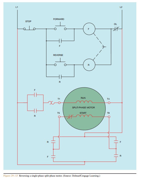
Notice that the control section is the same as that used for reversing three phase motors. In this article we are going to learn about the forward reverse starter. It reveals the components of the circuit as simplified forms as well as the power as well as signal links in between the tools. A schematic diagram of a forward reverse control for a single phase split phase motor is shown in figure 2913.


