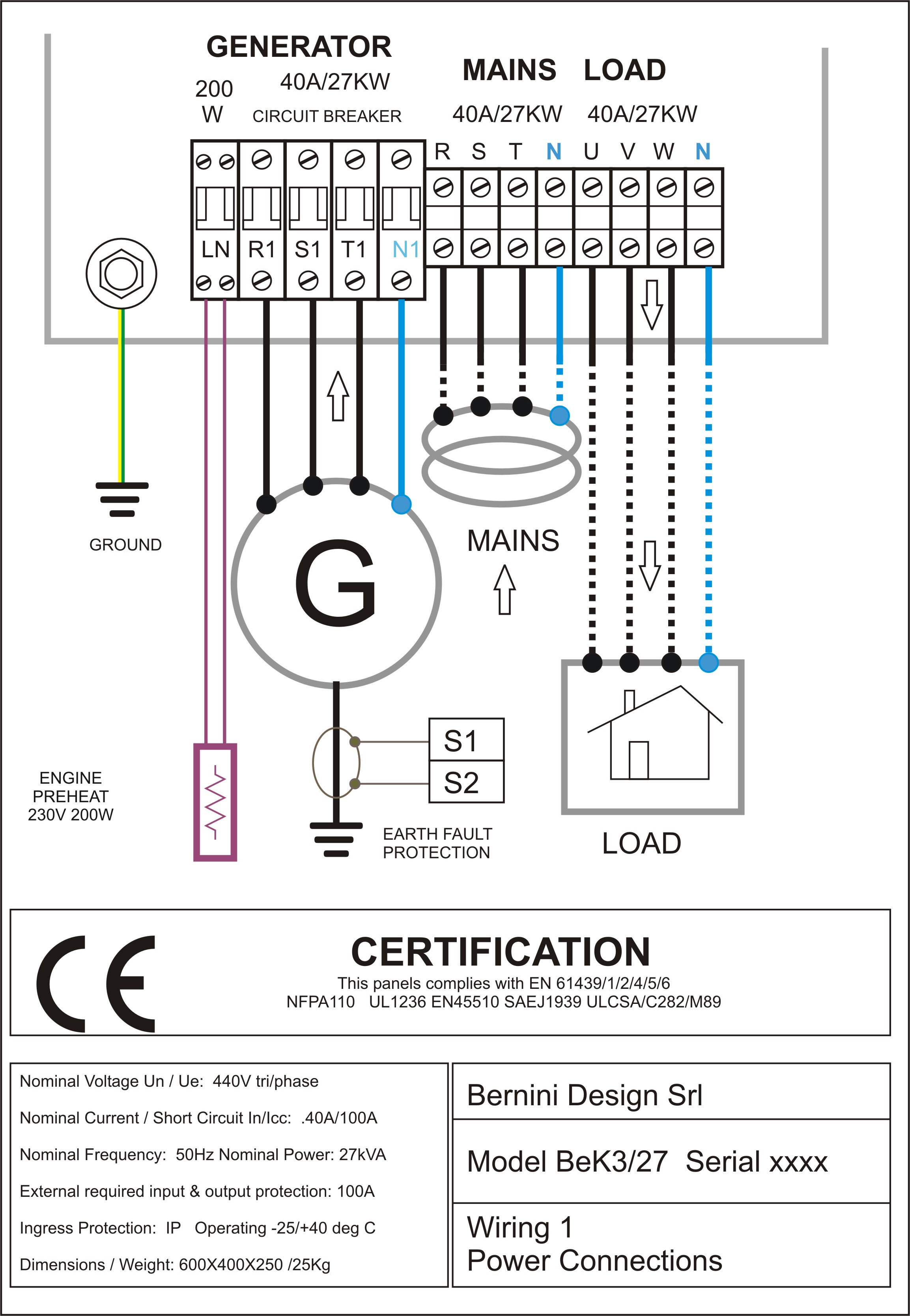
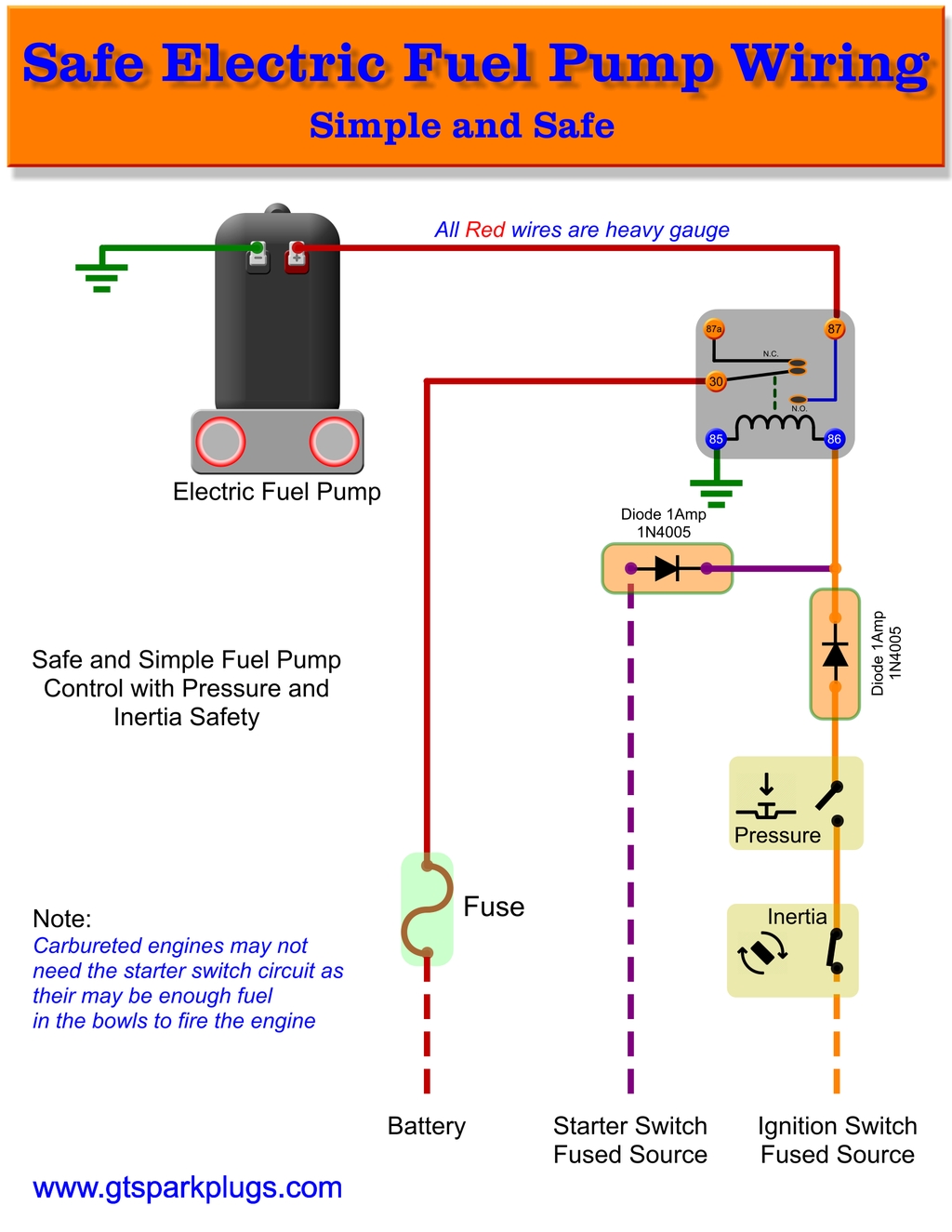
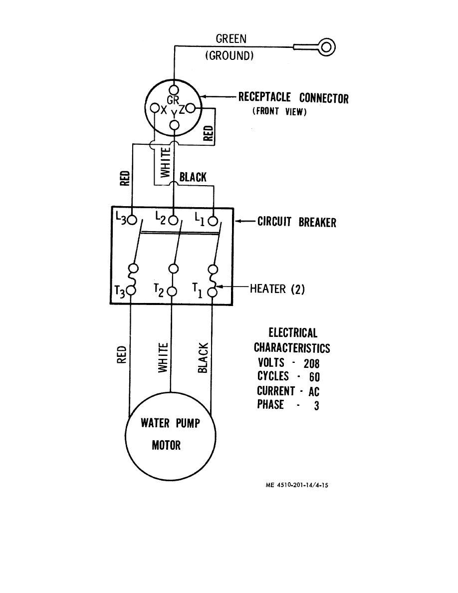
A wiring diagram is a simplified standard pictorial depiction of an electrical circuit. Here is the complete guide step by step.

Flygt Pump Wiring Diagrams Banyulangitimbal Down8 Zografisch Nl
Flygt submersible pump wiring diagram. In which i control a three phase submersible pump motor using magnetic contactor. Portable pump with hose coupling or flange for connection to the discharge pipe. A wiring diagram is a streamlined traditional photographic representation of an electrical circuit. The wiring connection of submersible pump control box is very simple. In this video i go over the differences of a 2 wire and a 3 wire submersible well pumpthis is associated with the starting components for the pump and whether they are located inside the motor. The jet aerator is designed for use in small to medium tanks and basins where the tasks include bodcod.
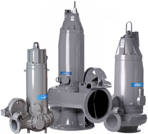
Flygt 3153 installation operation and maintenance manual. Dry installation vertical t vertical permanent dry pump installation. Install the drive unit in the pump housing. Page 63 tighten the greased screws. Flygt 5000 series flygt h 5100 the flygt h 5100 slurry pump is different. Portable submersible pump installation.
Flygt 3153 installation operation and maintenance manual. Flygt 2700 series flygt ds 2730 flygt ds 2730 is a electric submersible corrosion resistant sludge pump built to withstand the. Collection of 3 wire submersible pump wiring diagram. Flygt pump wiring diagram. Submersible pump starter use for starting of induction motor that connected with pump for lifting water from deep. Page 62 maintenance 8.
It shows the elements of the circuit as simplified forms and also the power as well as signal links between the devices. Not only a contactor but also i install the thermal overload relay which will protect the motor form burning in case of over current flow to the circuit. Flygt pump wiring diagram. Submersible pump starter increase in rapidly use in city because water lifting. Single phase submersible pump control box wiring diagram 3 wire submersible pump wiring diagram in submersible pump control box we use a capacitor a resit able thermal overload and dpst switch double pole single throw. A fit a new and greased o ring to the seal housing cover.
The submersible pump is installed in a dry pit with flange connection to suction and discharge piping. Assortment of single phase submersible pump starter wiring diagram. It reveals the elements of the circuit as streamlined forms and also the power and signal links in between the gadgets. Ws002056a b place the drive unit in the pump housing. 3 phase submersible pump wiring diagram. Installation operation and maintenance manual flygt jet aerator ja ja ja ja 3 contents tor is based on a submersible flygt pump and a flygt designed ejector system.


