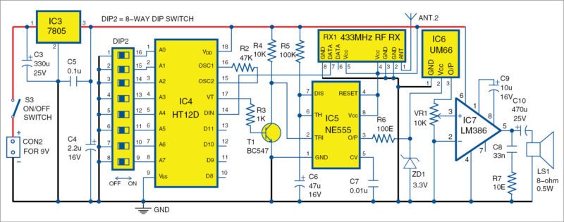
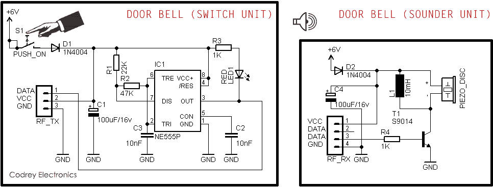
Circuit diagram of transmitter unit for the wireless doorbell dip1 is used to set the address bit either high or low. A um66 melody generator is connected at the output of the receiver circuit which will be activated when the receiver circuit receives signals from the transmitter.
Remote Control Using Wireless Doorbell Electronics For You
Circuit diagram of wireless doorbell. The wireless doorbell transmitter and receiver circuit are incorporated below. All 4 bit data pins ad8 through ad11 are connected to ground to reduce power consumption because 433mhz rf transmitter module tx1 uses on off key ook modulation. Circuit diagram and explanation. Hence it is suitable for large homes. The range of the transmission is fairly large. The circuit of the wireless bell shown here is easy to built and using only few easy to find low cost components.
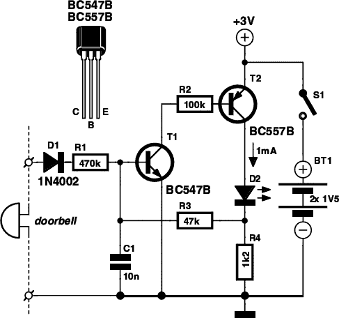
Here we can see that first 555 timer ic is configured in monostable mode means it will go high and low only once if triggered with trigger pin 2. All transistors are 2n3563 the u shape coil is a single half turn using a 1mm copper wire with 5mm diameter the most fundamental constituent is the transistor. Wireless doorbell this is diagram about circuit project. Wireless doorbell you can learn online. The advantage of using rf transmitter receiver based wireless doorbell is that it is very easy to design the circuit and implement. Above figure shows the circuit diagram for doorbell.


