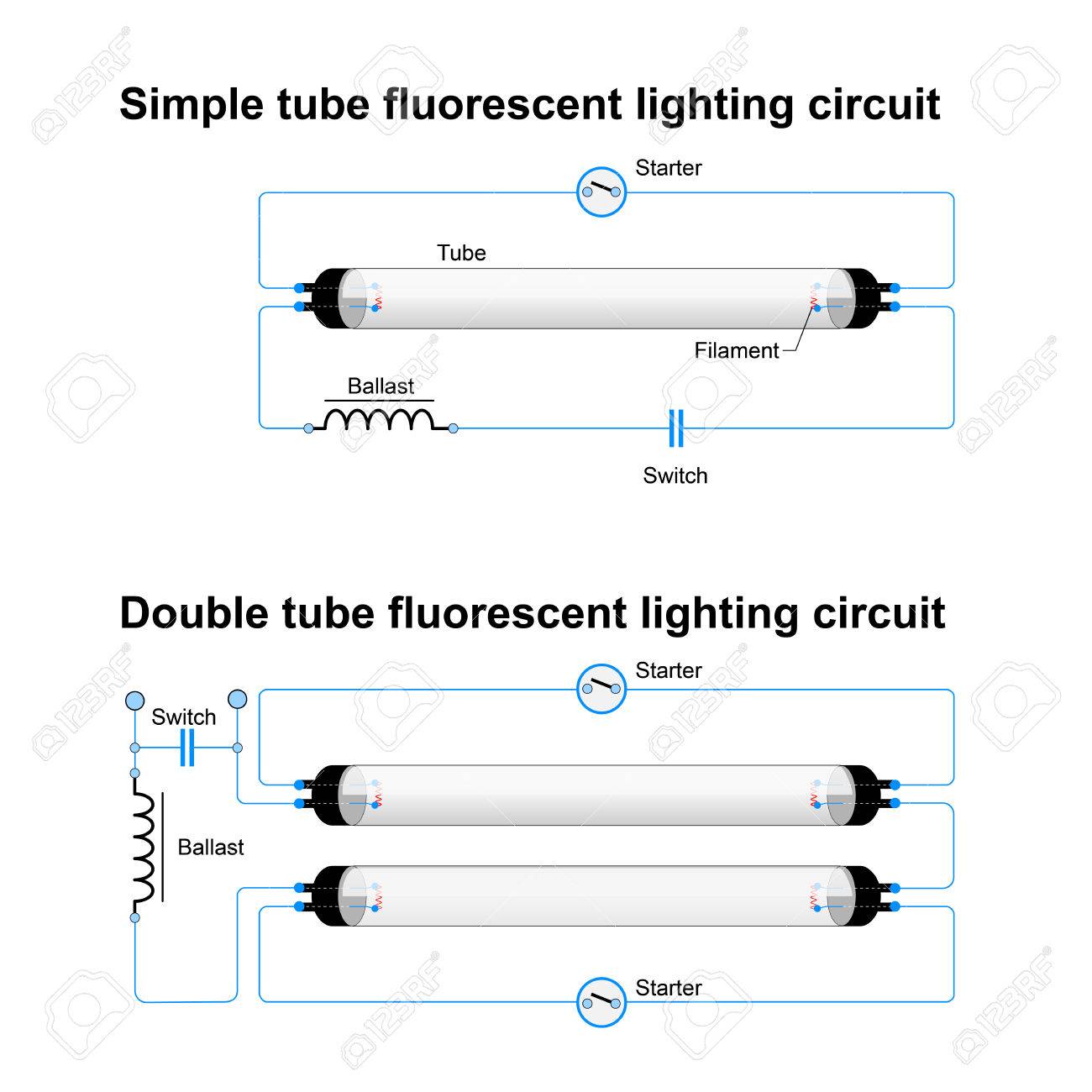
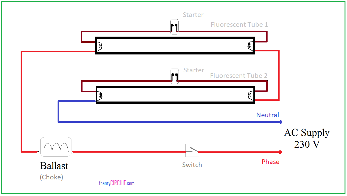
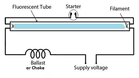
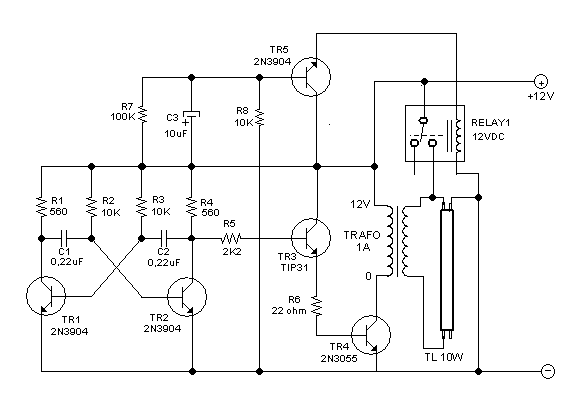
The classic fluorescent lamp design which has fallen mostly by the wayside used a special starter switch mechanism to light up the tube. It reveals the components of the circuit as streamlined forms and the power and also signal links in between the gadgets.
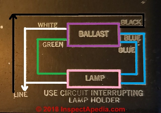
Fluorescent Light Ballast Repair Replacement Wiring
Fluorescent lighting circuit diagram. Circuit of a 40w fluorescent tube with 40w ballast and starter. Remove the two retaining screws from the cover of the fixture. The starter is like a key of fluorescent light because it is used to light up the tube. When the lamp first turns on the path of least resistance is through the bypass circuit and across the starter switch. An electronic ballast or electrical ballast is a device which controls the starting voltage and the operating currents of lighting devices. Lighting circuits with fluorescent tubes.
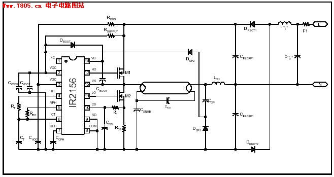
The hg symbol indicates that this lamp contains mercury. A wiring diagram is a simplified standard photographic depiction of an electric circuit. Assortment of fluorescent ballast wiring diagram. Step 2 remove the bulbs from an existing fluorescent light fixture in the garage. It does this through the principle of electrical gas dischargean electronic ballast will convert power frequency to a very high frequency to initialize the gas discharge process in fluorescent lamps by controlling. Please refer to the circuit diagram on the right as you read the following points.
This principle of the choke is exploited in lighting a fluorescent tube light. Turn off the breaker that powers the garage lighting circuit. Circuit with two fluorescent tubes 20w each with 40w ballast and two starters 20w each. Animation shows the circuit of the first kind of fluorescent lamp called the preheat. Compact fluorescent lamp with electronic ballast. You can see how this system works in the diagram below.
See how the ballast and starting switch work to strike an arc in the lamp. See the timing of the ac power. Go to back to content 5. When we connect the ac supply voltage to the circuit then the starter act like short circuited and current flow through those filament located at the first and second end of the tube light and the filament generate heat and it ionized the gas mercury vapor in the fluorescent tube lamp. A wiring diagram is a streamlined standard pictorial representation of an electric circuit. A matchstick left is shown for scale.
Two fluorescent tube lamps. What is electronic ballast. In the us this symbol is now required on all mercury containing fluorescent lamps. Switching lighting circuit operating diagram. Typical f71t12 100 w bi pin lamp used in tanning beds. Collection of led fluorescent tube replacement wiring diagram.
When an ac voltage is applied to a tube light fixture the voltage passes through the choke the starter and the filaments of the tube. It reveals the components of the circuit as streamlined shapes and also the power as well as signal connections between the devices. Remove the cover and set it and the retaining screws aside.


