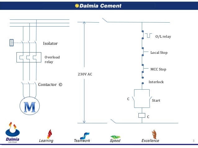
Basic wiring for motor control technical data. Wiring diagrams show the connections to the controller.
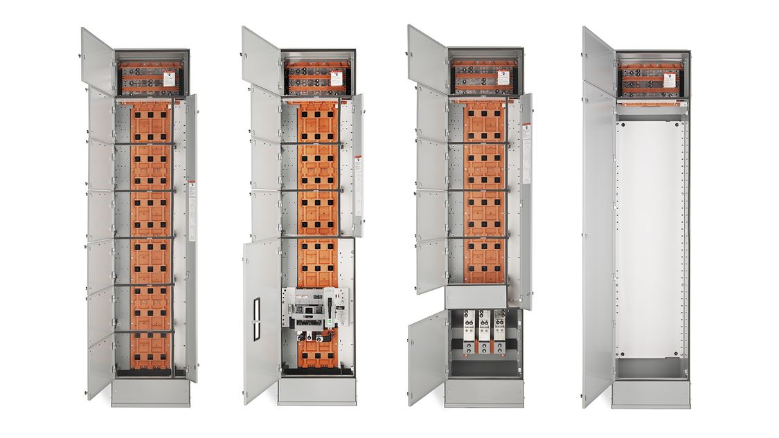
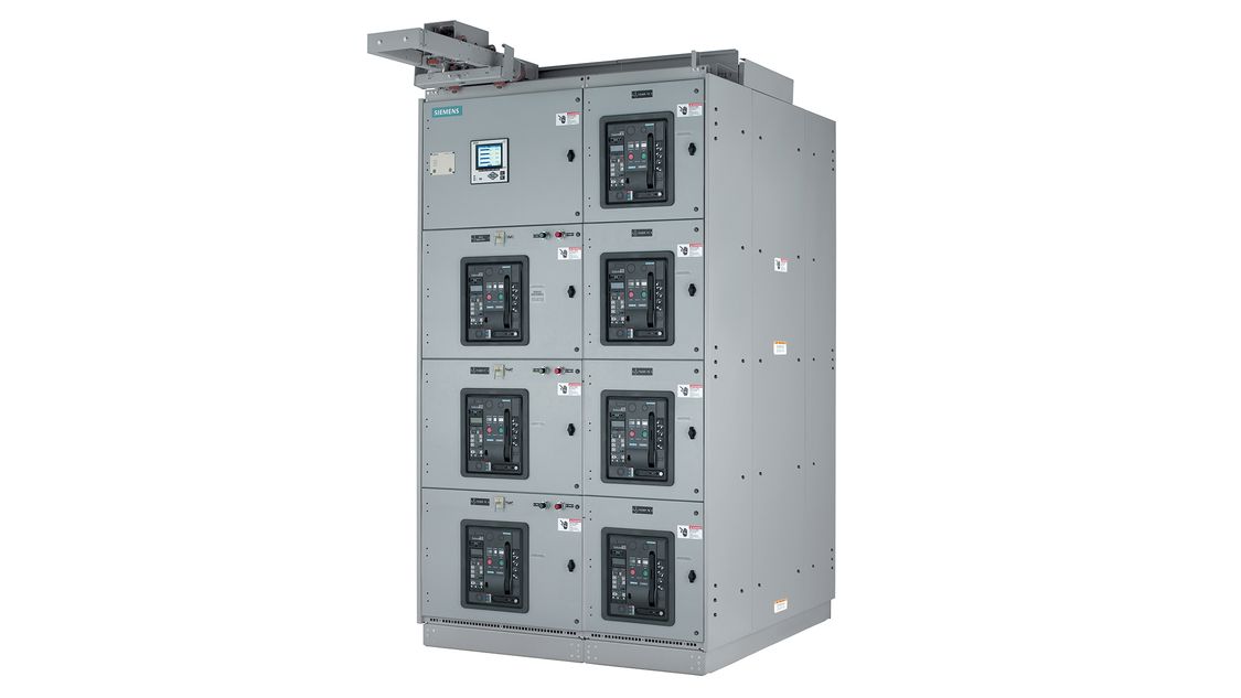
Low Voltage Motor Control Centers Low Voltage Power
Siemens motor control center wiring diagram. A wiring diagram is a streamlined conventional pictorial depiction of an electrical circuit. Power distribution systems used in large commercial and industrial applications can be complex. Siemens tlus talon temporary power outlet panel with a 20 30 and amp rec new siemens tlus talon temporary power outlet panel with a 20 30 and amp receptacle installed unmetered by siemens. New motor control center and power distribution board up to 7000 amperes. Literally a circuit is the path that allows electrical power to flow. Symbols that represent the constituents in the circuit and lines that represent the.
Power may be distributed through switchgears switchboards transformers and panelboards. Wiring diagrams comprise a couple of things. Use our tool to quickly find and download one line diagrams. Supporting documentation click here to view supporting documentation such as flyers brochures installation guides instruction manuals white papers specifications certifications and wiring diagrams for tiastar low voltage motor control centers. Collection of siemens motor control center wiring diagram. Receiving from factor a to point b.
Siemens motor control center wiring diagrams are at your fingertips within seconds. Use the tool below to quickly find and download one line diagrams. Siemens motor control center wiring diagram whats wiring diagram. Siemens motor control center wiring diagram a beginner s guide to circuit diagrams. Learn more about the motor control center standard catalog offering. An initial consider a circuit diagram might be confusing yet if you can review a train map you could read schematics.
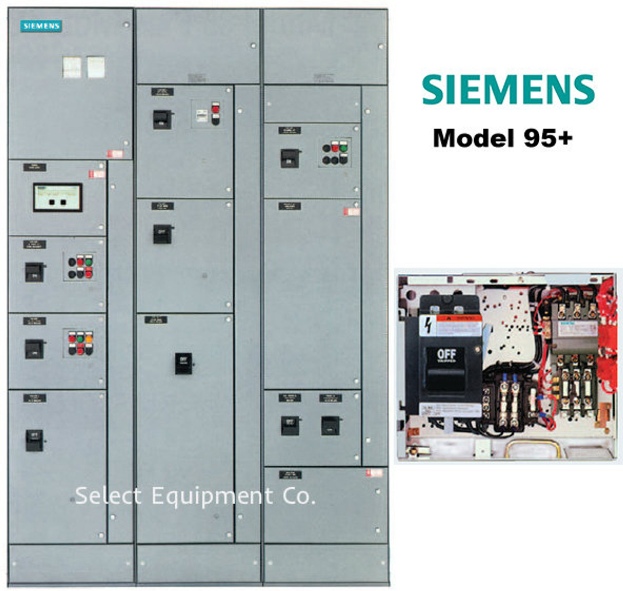
Siemens motor control center wiring diagrams at your fingertips within seconds. It reveals the elements of the circuit as streamlined forms as well as the power as well as signal links between the devices. Low voltage switchgear and other power distribution equipment. A wiring diagram is a schematic which uses abstract pictorial symbols to exhibit all of the interconnections of components in a system. Wiring diagrams sometimes called main or construction diagrams show the actual connection points for the wires to the components and terminals of the controller. Basics of motor control centers siemens on photo.
