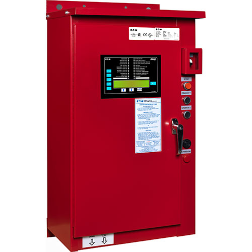
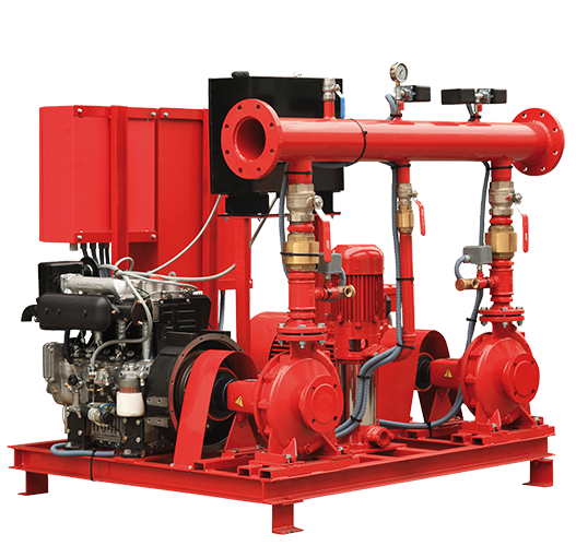
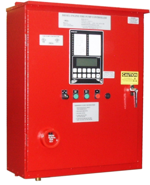
Accesstopower motorcontrol in this video we will look at the control wiring for a 3 phase pump panel and how a pump is controlled both in auto mode as well as hand mode. You must not connect conductors supplying power for pressure maintenance jockey or make up pumps to the fire pump controller per sec.

How To Wire Intermatic Pf1112 Freeze Control
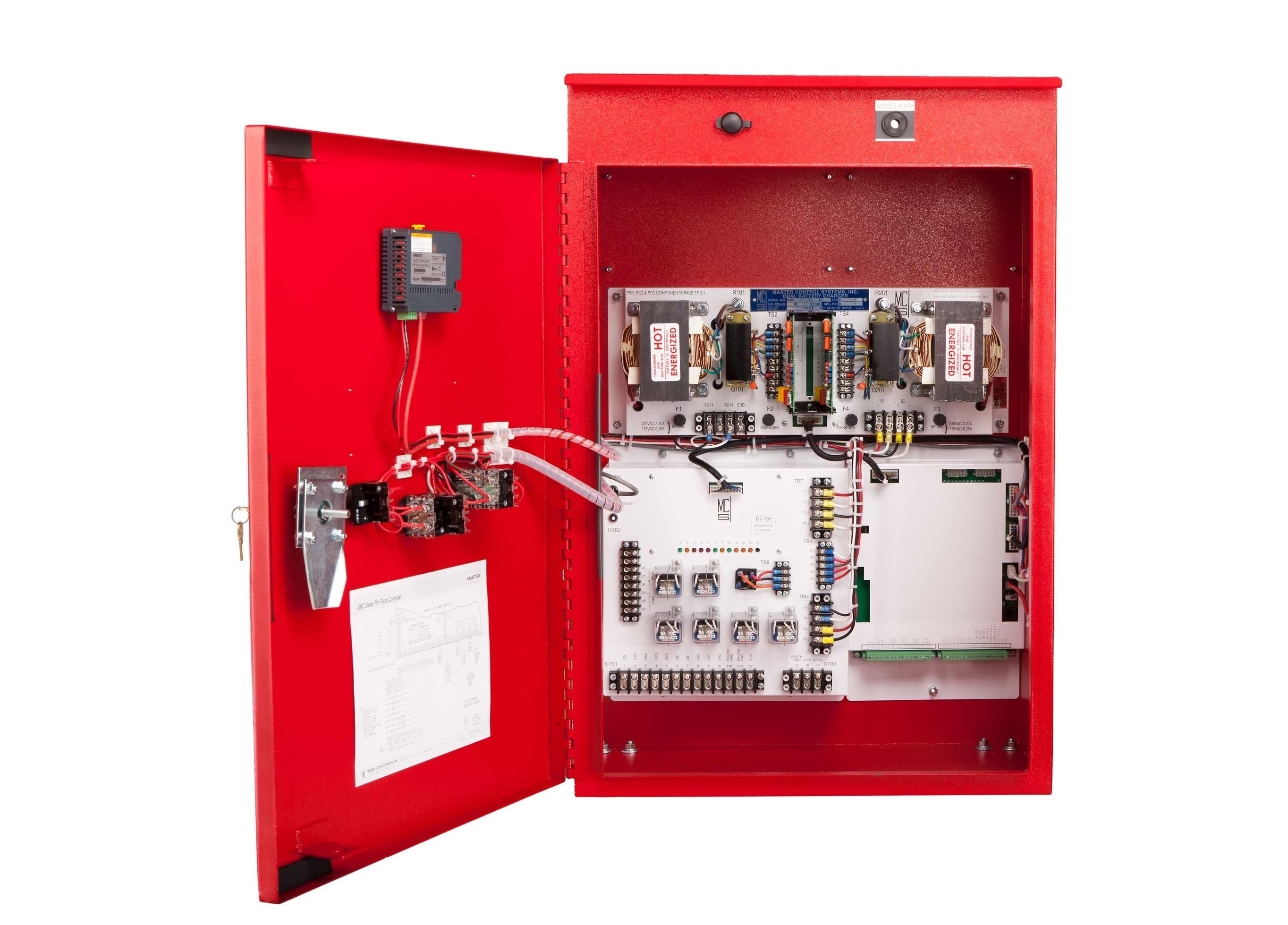
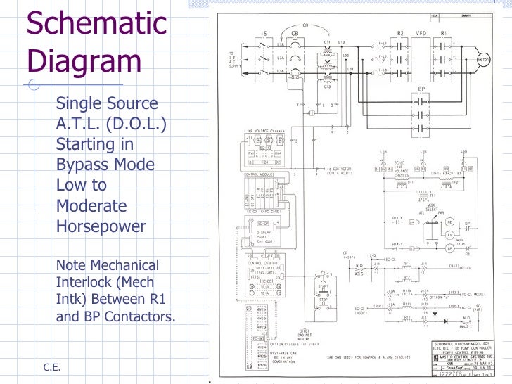
Fire pump control panel wiring diagram. In auto mode the pump. 7 344 in nfpa 20 and nec sec. Engines used for fire pump application do not feature the charger alternator. Find all fire pump controller drawings as well as jockey pump controller remote alarm panel and low suction shutdown controller drawings here. In a standard application not fire pump you are required to connect this terminal to jc 9 and to the dwl terminal of the belt alternator. Inputengine running detect input.
It shows the parts of the circuit as simplified shapes as well as the power as well as signal links between the devices. You are required to keep this terminal open. Variable speed jockey pump controller. Three phases variable speed pressure maintenance controller. Assortment of pump control panel wiring diagram schematic. A wiring diagram is a simplified traditional photographic depiction of an electric circuit.
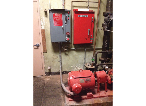
You cannot use the fire pump controller as a junction box for wiring to supply other electrical equipment. Wiring from the fire pump controller to the fire pump motor not installed through a building as covered in 6956b must be in rigid metal conduit intermediate metal conduit electrical metallic tubing liquidtight flexible metal conduit liquidtight flexible nonmetallic conduit type b listed type mc cable with an impervious covering or.
