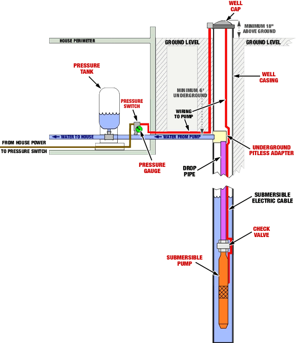
Typical submersible pump wiring diagrams connections. Now is where my confusion begins.

Ks 5903 Well Pump Pressure Switch Wiring Diagram View
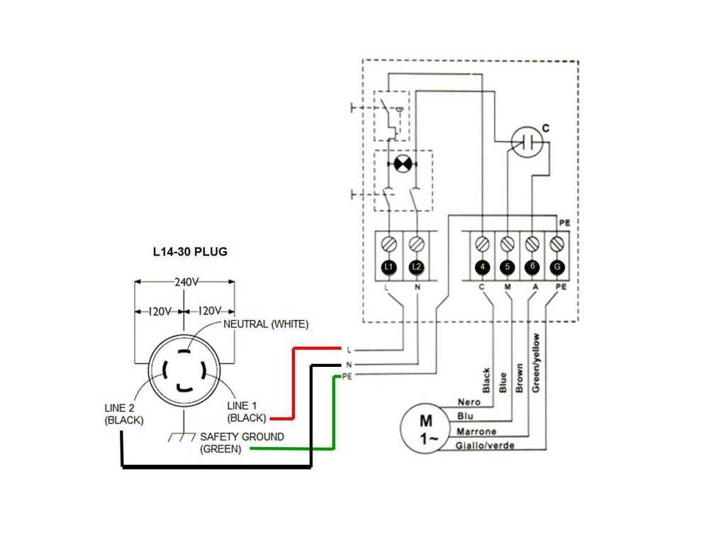
Wiring diagram of a submersible well pump. A submersible pump can be either two or three wire regardless of the voltage coming from the panel so start at your pump and follow the conduit back. The wiring connection of submersible pump control box is very simple. Black wires go to black wires and the green wire the ground goes to. A very first look at a circuit layout could be complicated however if you can review a subway map you could read schematics. Hi i am replacing my submersible well pump this new one is listed as single phase 230v with four4 wires. Two 2 are hot leads.
On 2018 08 19 by greg rhymer. 2 wire submersible well pump wiring diagram a newbie s overview of circuit diagrams. The last one 1 connects the capacitor motor. One 1 is a ground. The purpose is the very same. If the conduit runs into a control box before continuing to the water pressure switch chances are you have a three wire pump.
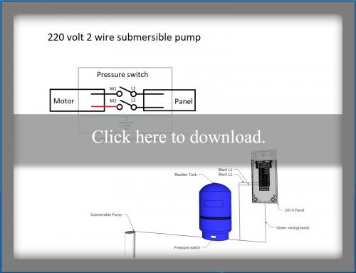
2 wire well pump diagrams are slightly easier to understand and are more straight forward to wire. Two wire well pump wiring diagrams. Single phase submersible pump control box wiring diagram 3 wire submersible pump wiring diagram in submersible pump control box we use a capacitor a resit able thermal overload and dpst switch double pole single throw. If it runs straight to the pressure switch it is a two wire. Getting from point a to point b. Submersible well pump wiring diagram awesome well pump control box architectural electrical wiring layouts reveal the approximate areas as well as affiliations of receptacles lighting and irreversible electric services in a structure.
Deep submersible well pumps will be either 2 wire or 3 wire well pumps and 3 wire well pumps will need a separately installed control box. Literally a circuit is the path that enables electrical power to. Here is the complete guide step by step.

