Just as in the three phase motor diagram the motor shows the power supply lines as being identified with the t. Otherwise the structure will not function as it ought to be.
Solved Draw The Wiring Diagram For A System That Contains
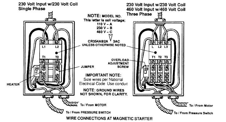
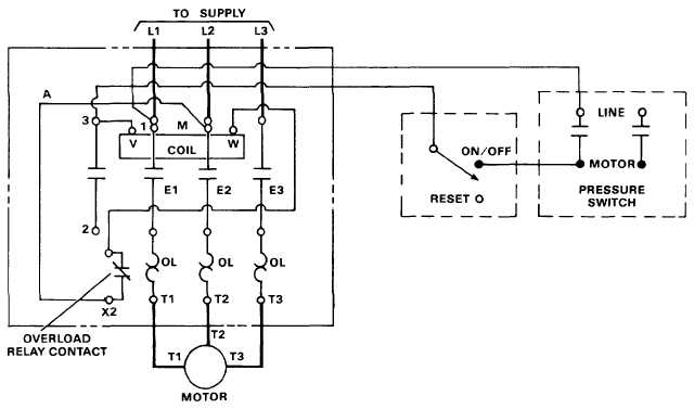
Electric motor starter wiring diagram. 3ph starter3ph motor line voltage control three phase 3ph motor starter controlling a three phase motor rev 08 aug 2006 the above wiring diagram assumes your magnetic starter has a 240v coil. Each part should be placed and connected with different parts in specific manner. In the above one phase motor wiring i first connect a 2 pole circuit breaker and after that i connect the supply to motor starter and then i do cont actor coil wiring with normally close push button switch and normally open push button switch and in last i do connection between capacitor. Wiring diagrams sometimes called main or construction diagrams show the actual connection points for the wires to the components and terminals of the controller. Wiring diagram for motor contactor best wiring diagram motor fresh. These diagrams are current at the time of publication check the wiring diagram supplied with the motor.
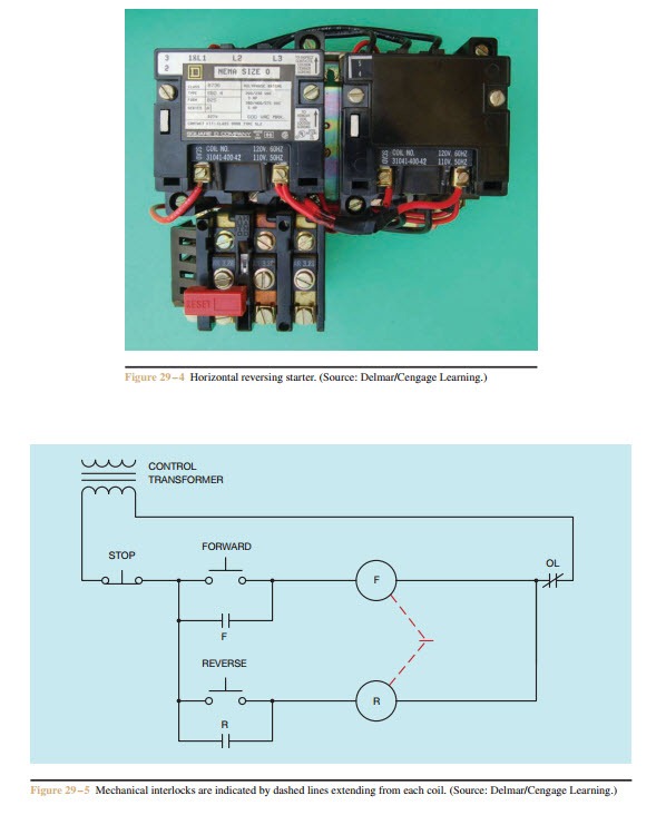
Basic wiring for motor control technical data. Inst maint wiringqxd 5032008 1002 am page 6. If you have a 120v coil instead of running a line from coil overload l2 you must run coil overload neutral. Starting a three phase motor. Wiring diagram since wiring connections and terminal markings are shown this type of diagram is helpful when wiring the. For most shore facility applications this is the case.
Honda gx390 electric start wiring diagram honda gx390 electric start wiring diagram every electric arrangement consists of various diverse parts. Motor starter schematic and wiring diagram. Refer to the motor manufacturers data on the motor for wiring diagrams on standard frame ex e ex d etc. A motor starter is a combination of devices used to start run and stop an ac induction motor based on commands from an operator or a controller. Level sensors and electric alternators94 class 9034 and 903994 pneumatic timing relays and solid state industrial timing relays95 96. Start stop 3 wire control.
Motor 3ct to 120 v separate control ot is a switch that opens. In north america an induction motor will typically operate at 230v or 460v 3 phase 60 hz and has a control voltage of 115 vac or 24 vdc. Wiring diagrams show the connections to the controller. The above diagram is a complete method of single phase motor wiring with circuit breaker and contactor. Single phase motor starter wiring diagram collections of 3 phase motor starter wiring diagram pdf. It reveals the parts of the circuit as simplified shapes and the power and.
The basic diagram view a shows a circle with two leads labeled t1 and t2. A wiring diagram is a simplified traditional photographic representation of an electric circuit. In many cases the single phase motors on board aplease check my motor wiring diagram mig welding.
Gallery of Electric Motor Starter Wiring Diagram


.jpg)