How to wire a phone jack voice or telephone rj 11 thru rj 14 usoc wiring diagram telephone wiring for a phone outlet is typically either 1 2 or 3 pairs 2 4 or 6 conductor. Telco connector with hook and loop fasteners accommodate 180 110 or 90 degree patch cord connectors on back of patch panel.

Cat5e Patch Panel With 24 Ports And 1 Rms Icc
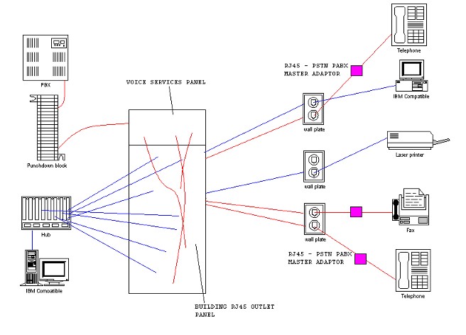
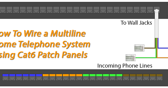
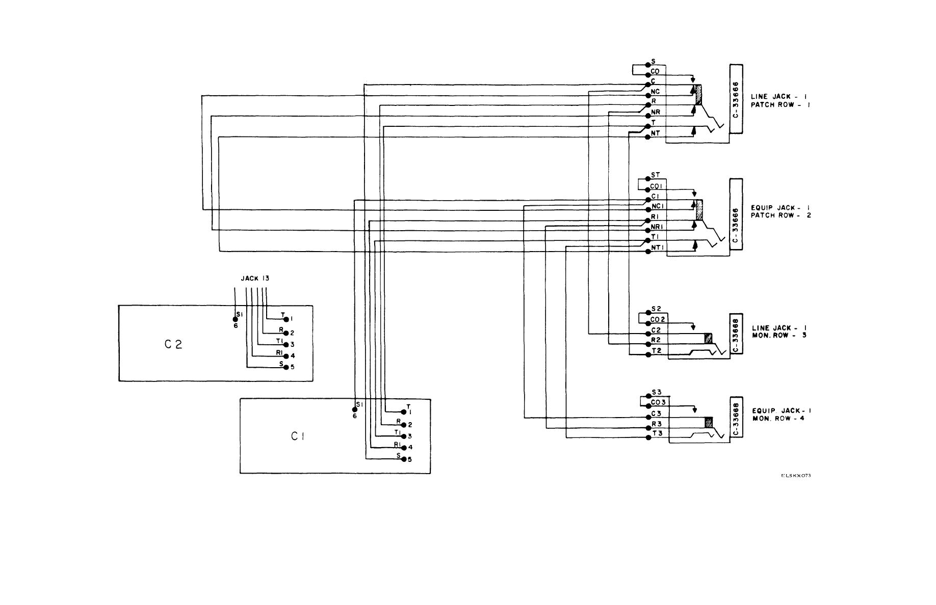
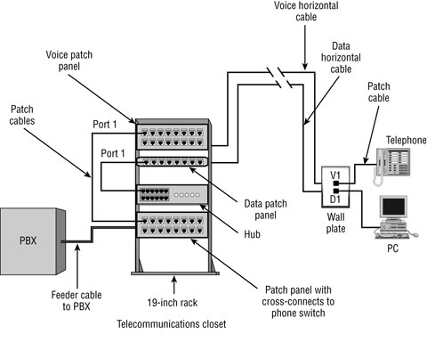
Voice patch panel wiring diagram. Consists of single female telco 50 pin25 pair connector with hook and loop fasteners wired for common active voice equipment. 24 rj45 ports with pins 4 and 5 active in each port. To do this youd daisy chain the incoming ho voice line to pins 4 and 5 on ports 7 12 as shown in the above wiring diagram then daisy chain the incoming ho fax line pair on pins 3 and 6. Ninety nine percent of the people that use them including us refer to the 8 pin modular phonedata plug ends as rj45 plugs. Youd need a different type of break out patch cable to make the connections. For these applications occ offers voice grade telco patch panels which break out to 24 rj45 jacks.
Most cable nowadays is utp unshielded twisted pair. Rj45 is actually a wiring scheme rather than a type of device. There are 4 remaining ports and i still need to connect the bt phone line into the patch panel but i am not sure how. You can then patch the voice line to upto 4 locations using standard patch leads at the patch panel. Lets start with some of the false but generally used terms. The wiring comes back to a 24 port patch panel which has all been successfully connected.
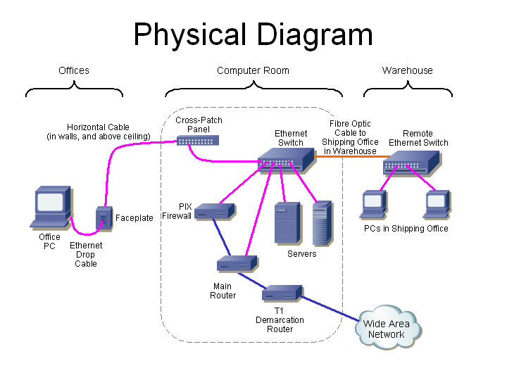
Voice data wiring knowledge document diagrams and discussion about commonly encountered items. Customers can easily patch their phone system into the permanent link by simply using patch cords and open ended cable assemblies punched down to a 110 block 66 block or 110 patch panel. There may be instances where you may need to connect to or transpose from the old quad cable. Does not require use of a punchdown tool.
Gallery of Voice Patch Panel Wiring Diagram